Dial-up pool: Difference between revisions
No edit summary |
No edit summary |
||
| Line 287: | Line 287: | ||
</pre><br /> | </pre><br /> | ||
</li> | </li> | ||
</ol> | |||
Congratulations! You now have your own voice network.<br /> | Congratulations! You now have your own voice network.<br /> | ||
Revision as of 16:59, 19 May 2020
Setting up your own Dial-up ISP with the ability to serve multiple clients is fairly straight forward but requires certain hardware, favorable network conditions, and a bit of patience.
This guide is intended to be as complete as possible and uses a Raspberry Pi computer for ease of use, but any computer with enough serial or USB ports that can run a modern Linux distribution will work.

Prerequisites
Hardware Requirements
- One or more hardware modems (no software modems or "winmodems")
- A Linux device (e.g. x86 computer, Raspberry Pi, etc.) to communicate with the modem(s) as the dial-in server
- A client device with a modem (any type, hardware or software)
- Some form of telephony connection between clients' modems and the ISP modems. I'll be using a software PBX and VoIP analog telephone adapters (ATAs)
The hardware used in this guide:
- Raspberry Pi 3B
- Modems:
- 3x USB to RS-232 serial adapters, ch341 chipset
- 3x DE-9 to DB-25 serial adapters
- 4x Linksys SPA-2102 analog telephone adapter (ATA) (Note: these can reach 50+°C! Don't stack them!)
-
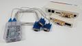
 Three external RS-232 and one USB modem
 -
 Modems with DB-25 to DE-9 adapters
 -
 Modem and USB to DE-9 adapter
 -
 Raspberry Pi, modems, and USB adapters
 -
 Four SPA-2102
 -
 Raspberry Pi 3b in a case


Software Requirements
- Raspbian, Debian, Ubuntu, or any modern Debian based Linux distribution (other flavors will work but the configuration will be different)
- ppp
- getty
- Asterisk
Choosing Modem Hardware
Modem hardware varies greatly, but this project doesn't require anything beyond standard protocols between your ISP and client modems (V.32, V.34, etc.).
This guide should work with any dial-up modem that presents itself as a serial device to the operating system, including cheap USB modems, ISA modems, PCI modems and of course external RS-232 serial modems.
Note: You will have a lot of trouble using a softmodem/winmodem! You are much better off using a hardware-based modem.
I'll be using three external serial modems + USB-to-RS-232 adapters and one USB modem. Using dedicated serial hardware has the advantage of being easy to troubleshoot and scaling up to dozens of lines (if you have enough desk space and USB ports).
Setting up the Dial-in Server
The dial-in server will answer calls from the modems and act as a proxy for access to network resources.
Using a Raspberry Pi
- Download the latest version of Raspbian Lite from raspberrypi.org and follow the installation instructions
- Before installing the SD card in your Raspberry Pi, enable SSH to avoid needed a mouse and keyboard:
- Mount the Raspberry Pi boot partition (most operating systems will do this automatically after writing the image)
- Create an empty file named
ssh(with no extension) in the same folder asconfig.txt - Safely eject the SD card
- Insert the SD card in your Raspberry Pi and connect the power and network cables
- Connect to the Raspberry Pi using SSH with the default username
piand passwordraspberry- If you know the IP address of the Pi, you can connect to it directly using your operating system's built-in SSH client (or PuTTY on Windows)
- If you don't know the IP address of the Pi, use a utility like Adafruit's Pi Finder to find its IP address and log in
Using a PC or other hardware
Install a Debian-based Linux distribution of your choice before proceeding. Installation instructions are beyond the scope of this guide; you should consult your distribution's instructions for help (Ubuntu, Debian).
The Telephone Network
We need a way to connect our ISP modem to clients. There are many ways to approach this:
- Use the actual PSTN (i.e. real phone lines)
- Use a PBX to provide local connectivity
- Build your own circuity (not covered here as it would require extra configuration)
- Build a fake PSTN using VoIP ATAs and a software PBX
I've gone with the fourth option. Here's the breakdown:
- Asterisk - a VoIP PBX - is configured on the dial-in server to accept connections from multiple SIP client accounts and route calls between them.
- Cisco-Linksys SPA-2102 ATA - which supports two phone lines - is set up as both of those SIP clients connected to the PBX.
- The ISP-side modem(s) connect to one phone line, and a client device to a second line.
This design can scale up to as many modems and clients as desired, just add more ATAs!
Asterisk Setup
- Install asterisk
- Append configuration for the SIP clients to the end of
/etc/asterisk/sip.conf(4 modems and 4 clients on 4 ATAs)[ata-modem1] context=default ; Using the default context because this is a simple design type=friend ; Allow calls to be placed and received to keep things simple secret=password ; Only the most secure passwords around here qualify=200 ; Qualify peer is no more than 200ms away host=dynamic ; This device registers with us directmedia=yes ; Send RTP directly to the peer to reduce latency and jitter nat=no ; Only use symmetric IP routing [ata-modem2] context=default type=friend secret=password qualify=200 host=dynamic directmedia=yes nat=no [ata-modem3] context=default type=friend secret=password qualify=200 host=dynamic directmedia=yes nat=no [ata-modem4] context=default type=friend secret=password qualify=200 host=dynamic directmedia=yes nat=no [ata-client1] context=default type=friend secret=password qualify=200 host=dynamic directmedia=yes nat=no [ata-client2] context=default type=friend secret=password qualify=200 host=dynamic directmedia=yes nat=no [ata-client3] context=default type=friend secret=password qualify=200 host=dynamic directmedia=yes nat=no [ata-client4] context=default type=friend secret=password qualify=200 host=dynamic directmedia=yes nat=no
- Edit
/etc/asterisk/extensions.confand make two changes:
Search for[default](should be around line 672) and comment outinclude => demo
Underneath that line, add the new lines for the specific modems and the dial pool
exten => 881,1,Dial(SIP/ata-modem1, 30)
exten => 882,1,Dial(SIP/ata-modem2, 30)
exten => 883,1,Dial(SIP/ata-modem3, 30)
exten => 884,1,Dial(SIP/ata-modem4, 30)
exten => _X!,1,Dial(SIP/ata-modem1&SIP/ata-modem2&SIP/ata-modem3&SIP/ata-modem4, 30)
The _X! tells this dial plan rule to match any number a client dials and send the call to all of the ata-modem[1-4] clients simultaneously with a 30 second timeout. If you want to use a specific modem dial its extension and only that modem will ring.
- Enable the asterisk service so it starts on boot
sudo systemctl enable asterisk
-
Start Asterisk
sudo systemctl start asterisk
sudo apt-get install asterisk
ATA Configuration
Using a Unlocked SPA-2102. If your device is locked follow these instructions
(Settings below are confirmed working on firmware firmware 5.2.5 and 5.1.13)
Example of configuring a client line. (Same settings for modem line, just a different username/password)
Lets start with factory default configuration and enabling web-based management.
- Connect a phone to LINE 1
- Dial **** to enter the configuration menu
- Dial 73738# then 1# then hang up. The unit is now factory reset
- Connect the Internet ethernet connection to your local network
- Dial **** to enter the configuration menu
- Dial 7932# then 1# then 1 then hang up. The web interface is now accessible from the 'Internet' side of the ATA
- Dial **** to enter the configuration menu
- Dial 110# to hear the IP address of your ATA
On a PC point your web browser at the IP of the ATA to load the web configuration. Several options need to be changed.
- Click "Admin Login"
- Click "Advanced"
- (Optiona) Click "WAN Setup" if you need to change the IP address of the ATA
- Click the "Voice" tab
- Click "Line 1"
- Change "Network Jitter Level" to "extremely high" or "high"
- Change "Jitter Buffer Adjustment" to "disable"
- Set "Proxy" to the IP address of the Raspberry Pi running askterisk
- Set "User ID" to the username of the SIP user you are configuring, "ata-client3"
- Set "Password" to the password of that user
- Change "Call Waiting Serv" to "no"
- Change "Three Way Call Serv" to "no"
- Change "Preferred Codec" to "G711u"
- Change "Use Pref Codec Only" to "yes"
- Change "Silence Supp Enable" to "no"
- Change "Silence Threshold" to "high"
- Change "Echo Canc Enable" to "no"
- Change "Echo Canc Adapt Enable" to "no"
- Change "Echo Supp Enable" to "no"
- Change "FAX CED Detect Enable" to "no"
- Change "FAX CNG Detect Enable" to "no"
- Change "FAX Process NSE" to "no"
- Change "FAX Enable T38" to "no"
- Click "Submit All Changes"
Repeat for Line 2 if you need another line.
When your ATA is first configured to connect to the SIP proxy (Asterisk) you will see output similar to this on the Asterisk console:
sudo asterisk -rvvvv
raspberrypi*CLI>
[Apr 27 04:08:29] NOTICE[573]: chan_sip.c:24884 handle_response_peerpoke: Peer 'ata-client1' is now Reachable. (13ms / 200ms)
[Apr 27 04:08:29] NOTICE[573]: chan_sip.c:24884 handle_response_peerpoke: Peer 'ata-client2' is now Reachable. (5ms / 200ms)
Verifying functionality
- Open the Asterisk console to confirm your ATA lines are registered
sudo asterisk -rvvvvraspberrypi*CLI> sip show peers Name/username Host Dyn Forcerport Comedia ACL Port Status Description ata-client1/ata-client1 10.1.0.126 D No No 5060 OK (7 ms) ata-client2/ata-client2 10.1.0.126 D No No 5061 OK (7 ms) ata-client3/ata-client3 10.1.0.125 D No No 5060 OK (9 ms) ata-client4/ata-client4 10.1.0.125 D No No 5061 OK (10 ms) ata-modem1/ata-modem1 10.1.0.108 D No No 5060 OK (8 ms) ata-modem2/ata-modem2 10.1.0.108 D No No 5061 OK (7 ms) ata-modem3/ata-modem3 10.1.0.128 D No No 5060 OK (7 ms) ata-modem4/ata-modem4 10.1.0.128 D No No 5061 OK (8 ms) 8 sip peers [Monitored: 8 online, 0 offline Unmonitored: 0 online, 0 offline]
If you make changes to your configuration after starting Asterisk, you can use thereloadcommand in the console to reload the configuration. - Confirm clients can dial modems directly. Using a phone connected to one of the client lines dial 881# (the # tells the ATA you are done dialing), the first modem line should ring.
- Confirm clients can dial the modem pool. Dial 888# (or any number except the direct modem lines) and all modem lines should ring at once.
If you take a look at the asterisk console when dialing the pool you should see output like this:
raspberrypi*CLI>
  == Using SIP RTP CoS mark 5
       > 0x73a18d80 -- Strict RTP learning after remote address set to: 10.1.0.125:16386
    -- Executing [888@default:1] Dial("SIP/ata-client3-00000005", "SIP/ata-modem1&SIP/ata-modem2&SIP/ata-modem3&SIP/ata-modem4, 30") in new stack
  == Using SIP RTP CoS mark 5
  == Using SIP RTP CoS mark 5
  == Using SIP RTP CoS mark 5
  == Using SIP RTP CoS mark 5
    -- Called SIP/ata-modem1
    -- Called SIP/ata-modem2
    -- Called SIP/ata-modem3
    -- Called SIP/ata-modem4
    -- SIP/ata-modem3-00000008 is ringing
    -- SIP/ata-modem1-00000006 is ringing
    -- SIP/ata-modem4-00000009 is ringing
    -- SIP/ata-modem2-00000007 is ringing
Congratulations! You now have your own voice network.
The Dial-in Server
- Install your Debian-based Linux distribution of choice (Raspbian covered above)
- Update to latest packages and reboot if required
- Connect a USB to RS-232 adapter and confirm it shows up as /dev/ttyUSBXXX (Run
ls /dev/ordmesgto check). In my case, it presents as/dev/ttyUSB0
My serial adapters are "QinHeng Electronics HL-340 USB-Serial adaptor" perlsusb -v - Install ppp (and getty if your distro doesn’t have it by default)
sudo apt-get install ppp mgetty
- Create a systemd service for mgetty, by editing
/lib/systemd/system/[email protected](note the @) with your text editor of choice as root or sudo.[Unit] Description=External Modem %I Documentation=man:mgetty(8) Requires=systemd-udev-settle.service After=systemd-udev-settle.service [Service] Type=simple ExecStart=/sbin/mgetty /dev/%i Restart=always PIDFile=/var/run/mgetty.pid.%i [Install] WantedBy=multi-user.target
-
Configure mgetty by editing
/etc/mgetty/mgetty.config
Comment out everything except the debug level, and append the section for configuring the serial devices: I have 3 USB to serial devices (ttyUSB0, ttyUSB1, ttyUSB2) and one USB modem ttyACM0debug 9 port ttyUSB0 port-owner root port-group dialout port-mode 0660 data-only yes ignore-carrier no toggle-dtr yes toggle-dtr-waittime 500 rings 1 speed 115200 modem-check-time 160 port ttyUSB1 port-owner root port-group dialout port-mode 0660 data-only yes ignore-carrier no toggle-dtr yes toggle-dtr-waittime 500 rings 2 speed 115200 modem-check-time 60 port ttyUSB2 port-owner root port-group dialout port-mode 0660 data-only yes ignore-carrier no toggle-dtr yes toggle-dtr-waittime 500 rings 3 speed 115200 modem-check-time 60 port ttyACM0 port-owner root port-group dialout port-mode 0660 data-only yes ignore-carrier no toggle-dtr yes toggle-dtr-waittime 500 rings 4 speed 115200 modem-check-time 60
Theringsparameter tells mgetty to answer the call after that many rings. They increase in the config so that all the modems dont try to answer at once, and you can prioritize which modems you want to be used most often. - Enable the mgetty service so it starts on boot for each device:
sudo systemctl enable [email protected] sudo systemctl enable [email protected] sudo systemctl enable [email protected] sudo systemctl enable [email protected]
-
Start mgetty:
sudo systemctl start [email protected] sudo systemctl start [email protected] sudo systemctl start [email protected] sudo systemctl start [email protected]
- Configure ppp by editing
/etc/ppp/options
Like above, comment out everything except these settings:# Define the DNS server for the client to use ms-dns 8.8.8.8 # async character map should be 0 asyncmap 0 # Require authentication auth # Use hardware flow control crtscts # We want exclusive access to the modem device lock # Show pap passwords in log files to help with debugging show-password # Require the client to authenticate with pap +pap # If you are having trouble with auth enable debugging debug # Heartbeat for control messages, used to determine if the client connection has dropped lcp-echo-interval 30 lcp-echo-failure 4 # Cache the client mac address in the arp system table proxyarp # Disable the IPXCP and IPX protocols. noipx
- Create a device option file for each device by editing:
/etc/ppp/options.ttyUSB0
local lock nocrtscts 192.168.32.1:192.168.32.2 netmask 255.255.255.252 noauth proxyarp lcp-echo-failure 60
/etc/ppp/options.ttyUSB1
local lock nocrtscts 192.168.32.5:192.168.32.6 netmask 255.255.255.252 noauth proxyarp lcp-echo-failure 60
/etc/ppp/options.ttyUSB2
local lock nocrtscts 192.168.32.9:192.168.32.10 netmask 255.255.255.252 noauth proxyarp lcp-echo-failure 60
/etc/ppp/options.ACM0
local lock nocrtscts 192.168.32.13:192.168.32.14 netmask 255.255.255.252 noauth proxyarp lcp-echo-failure 60
It is important that the IP adresses do not overlap across the device configurations. I'm using small /30 subnets (4 IP addresses, 2 usable) to separate each client.
- Create the user for PAP authentication:
sudo useradd -G dialout,dip,users -m -g users -s /usr/sbin/pppd dial - Set a password:
sudo passwd dial (I used dial, same as the username)
- Edit
/etc/ppp/pap-secretsand append the username and password (same as you entered above, quotes included):
dial * "dial" * - Enable packet forwarding for IP4 by editing
/etc/sysctl.conf:net.ipv4.ip_forward=1 -
The last step for the dial-up server is to configure the firewall to allow traffic forwarding from PPP out onto the network (and off to the Internet).
- On Linux distributions with iptables, you need to add a line to
/etc/rc.localto enable masquerading. If your Ethernet interface is named eth0, you would add this line:iptables -t nat -A POSTROUTING -s 192.168.32.0/24 -o eth0 -j MASQUERADE -
On modern Ubuntu installs, ufw is used as a frontend to iptables, so the procedure is a bit different. Follow this guide, but you can omit
-o eth0and use-s 192.168.32.0/24.
- On Linux distributions with iptables, you need to add a line to
sudo apt-get update
sudo apt-get upgrade
sudo reboot
Connecting with a client
Connect a client device to a client line on an ATA and configure it to use PPP authentication with the username dial and password dial
To dial a specific modem use the number 881# for modem one. To dial the modem pool dial any other number such as 888#, 18008276364, 17607067425 etc
Troubleshooting
When using an external modem, the choice of USB to RS-232 adapter seems to be crucial. There aren't many requirements, but you must use an adapter that supports hardware flow control.
If you need to purchase an adapter, you can either get one that explicitly says it supports hardware flow control ($$$), or play the eBay lottery and buy a half-dozen different models and hope one of them works.
To troubleshoot modem communication and baud rate settings, use minicom (or screen) to open a session over serial and try different settings (or read your modem's manual!). Sending the command 'AT' followed by a new line should result in your modem replying 'OK'.
If you're getting nothing at all out of your modem, perform a serial loopback test
If mgetty is not answering incoming calls, it may be having trouble communicating with your modem. Check the logs in /var/log/mgetty/ to determine the problem. You may need to set a modem initialization string in the mgetty device config file, so check your modem's manual for help on this.
If you are having trouble with Asterisk please consult voip-info.org as Asterisk is quite complex and its troubleshooting is outside the scope of this guide.
That said here is a successful call to 888 (pool) as an example:
raspberrypi*CLI>
  == Using SIP RTP CoS mark 5
       > 0x73a18d80 -- Strict RTP learning after remote address set to: 10.1.0.125:16386
    -- Executing [888@default:1] Dial("SIP/ata-client3-00000005", "SIP/ata-modem1&SIP/ata-modem2&SIP/ata-modem3&SIP/ata-modem4, 30") in new stack
  == Using SIP RTP CoS mark 5
  == Using SIP RTP CoS mark 5
  == Using SIP RTP CoS mark 5
  == Using SIP RTP CoS mark 5
    -- Called SIP/ata-modem1
    -- Called SIP/ata-modem2
    -- Called SIP/ata-modem3
    -- Called SIP/ata-modem4
    -- SIP/ata-modem3-00000008 is ringing
    -- SIP/ata-modem1-00000006 is ringing
    -- SIP/ata-modem4-00000009 is ringing
    -- SIP/ata-modem2-00000007 is ringing
       > 0x73a31a78 -- Strict RTP learning after remote address set to: 10.1.0.108:16386
    -- SIP/ata-modem2-00000007 answered SIP/ata-client3-00000005
    -- Channel SIP/ata-modem2-00000007 joined 'simple_bridge' basic-bridge <3d2328ec-ef87-431e-be12-2dd9b84b6319>
    -- Channel SIP/ata-client3-00000005 joined 'simple_bridge' basic-bridge <3d2328ec-ef87-431e-be12-2dd9b84b6319>
       > Bridge 3d2328ec-ef87-431e-be12-2dd9b84b6319: switching from simple_bridge technology to native_rtp
       > Remotely bridged 'SIP/ata-client3-00000005' and 'SIP/ata-modem2-00000007' - media will flow directly between them
       > 0x73a31a78 -- Strict RTP learning after remote address set to: 10.1.0.108:16386
       > 0x73a18d80 -- Strict RTP learning after remote address set to: 10.1.0.125:16386
[call proceeds then ends below]
    -- Channel SIP/ata-modem2-00000007 left 'native_rtp' basic-bridge <3d2328ec-ef87-431e-be12-2dd9b84b6319>
    -- Channel SIP/ata-client3-00000005 left 'native_rtp' basic-bridge <3d2328ec-ef87-431e-be12-2dd9b84b6319>
  == Spawn extension (default, 888, 1) exited non-zero on 'SIP/ata-client3-00000005'
       > 0x73a18d80 -- Strict RTP learning after remote address set to: 10.1.0.125:16386