| Home | Current Systems | Former STK Products | EOL Systems | Components | General Info | Search | Feedback |
|
|
Sun System Handbook - ISO 4.1 October 2012 Internal/Partner Edition | ||
|
|||
Sun Storage 2500-M2 Series Array LEDs
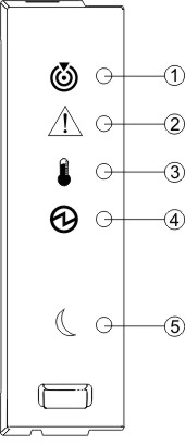
Front Panel LEDs
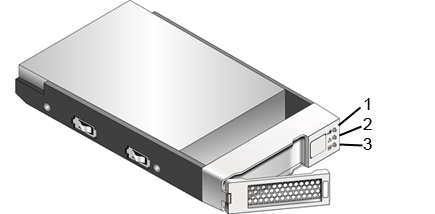
Front Panel LEDs - Disk Drives | ||||||||||||||||||||||||||||||||||||||||||||||||||||||||||||||||||||||||||||||||||||||||||||||||||||||||||||||||||||||||||||||||||||||||||||||||||||||||||||||||||||||||||||||||||||||||||||||||
| Disk Drive LED Description | |||
|---|---|---|---|
| Location |
LED Name
|
Color
|
General Behavior
|
|
1
|
Service Action Allowed
|
Blue | Off - The disk drive cannot be removed from the tray. On - The disk drive can be safely removed from the tray. |
|
2
|
Service Action Required
|
Amber | Off - Normal condition. On - An error has occurred. |
|
3
|
Drive Ready/Activity
|
Green | Off - The power is turned off. On - The power is on and the disk drive is operating normally. Blinking - Disk drive I/O activity is taking place. |
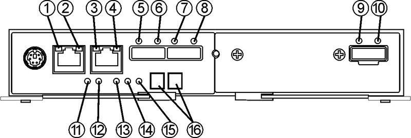
| Location | LED Name | Color | On | Off |
|---|---|---|---|---|
|
1
|
Ethernet port 1 Link Rate | Green | Port speed is 1000 Mb/sec | Port speed is 10/100 Mb/sec |
|
2
|
Ethernet port 1 Link Active | Green | The link is up. LED blinks with transmit or receive activity. | The link is down or not active. |
|
3
|
Ethernet port 2Link Rate | Green | Port speed is 1000 Mb/sec | Port speed is 10/100 Mb/sec |
|
4
|
Ethernet port 2Link Active | Green | The link is up. LED blinks with transmit or receive activity. | The link is down or not active. |
|
5
|
Host Link 2 Service Action Required | Amber | Indicates a fault on one of the ports. | Amber and green LEDs off indicates cable unplugged. |
|
6
|
Host Link 2 Activity | Green | All links operating. | Amber and green LEDs off indicates cable unplugged. |
|
7
|
Host Link 1 Service Action Required | Amber | Indicates a fault on one of the ports. | Amber and green LEDs off indicates cable unplugged. |
|
8
|
Host Link 1Activity | Green | All links operating. | Amber and green LEDs off indicates cable unplugged. |
|
9
|
Expansion Fault | Amber | Indicates a fault on one of the links. | Amber and green LEDs off indicates cable unplugged. |
|
10
|
Expansion Activity | Green | All links operating. | Amber and green LEDs off indicates cable unplugged. |
|
11
|
Battery Fault | Amber | Battery failure | Battery is operating normally. |
|
12
|
Battery Charging | Green | Flashes at 1Hz during charging. On indicates fully charged. | Battery faulted or operating without a battery. |
|
13
|
Service Action Allowed | Blue | The controller module can be removed safely from the controller tray (Defaults to On at power up.) | Controller module cannot be safely removed from the controller tray (Software turns this LED Off during boot). |
|
14
|
Service Action Required (Fault) | Amber | Indicates a fault was detected on the board (Defaults to On at power up.) | Power up self-test sequence has completed. |
|
15
|
Cache Active / Cache Offloading | Green | Battery backup is enabled to support caching activity. If AC power fails, this LED indicates cache offloading is occurring. | Cache is inactive or the controller has been removed from the controller tray. |
|
16
|
7-Segment Display | Green | Displays the tray ID and error codes. See Sun Storage 2500-M2 Arrays Hardware Installation Guide for error code definitions. | |
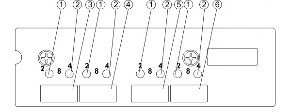
| Location | Description | Notes |
|---|---|---|
|
1
|
Fibre Channel (FC) Link Status LED | LED 1 Off, LED 2 Off = No Link LED 1 On, LED 2 Off = 2 Gb/sec Link LED 1 Off, LED 2 On = 4 Gb/sec Link LED 1 On, LED 2 On = 8Gb/sec Link |
|
2
|
Fibre Channel (FC) Link Status LED | LED 1 Off, LED 2 Off = No Link LED 1 On, LED 2 Off = 2 Gb/sec Link LED 1 Off, LED 2 On = 4 Gb/sec Link LED 1 On, LED 2 On = 8Gb/sec Link |
|
3
|
FC Host Port (Channel 3) | |
|
4
|
FC Host Port (Channel 4) | |
|
5
|
FC Host Port (Channel 5) | |
|
6
|
FC Host Port (Channel 6) |
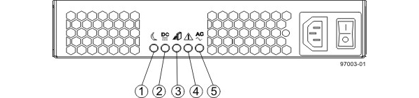
|
Location
|
LED Name
|
Color
|
On
|
Off
|
|---|---|---|---|---|
|
1
|
Standy Power | Green | Tray is in Standby mode (5V), and DC power is not available. | Tray is not in Standy mode, and DC power is available. |
|
2
|
DC Power | Green | DC power from the power-fan module is available and within the specified limits. | DC power from the power-fan module is not available. |
|
3
|
Service Action Allowed | Blue | Power-fan module can be removed safely from the tray. | The power-fan module cannot be removed from the tray. |
|
4
|
Service Action Required | Amber | .Indicates a fault when (a) the power cord is plugged in, the power switch is on and the power supply is not correctly connected to the midplane, or (b) power cord is plugged in, the power supply is correctly seated in the midplane, and a power supply or blower fault or over-temperature condition exists. | Normal status |
|
5
|
AC Power | Green | AC power to the power-fan module is present. | AC power to the power-fan module is not present. |
|
Copyright © 2012 Sun Microsystems, Inc. All rights reserved. Feedback | |||