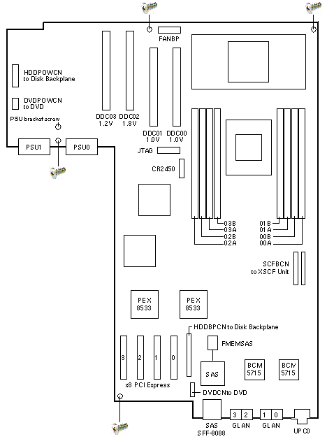
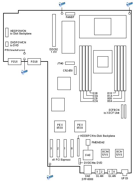
System Board
| 541-3302 |
541-3674 |
541-4281 |
541-4282 |
4-Core 2.52GHz
CA07082-K017 |
2-Core 2.52GHz
CA07082-K047 |
4-Core 2.75GHz
CA07082-K057 |
2-Core 2.75GHz
CA07082-K067 |

|
SPARC Enterprise M3000 Codename: Ikkaku |
Notes
- Unfasten the four screws shown to remove the system board.
- Screw locations silkscreened with a screw image fasten the system board
to the tray.
- It is not necessary to unfasten the screw locations silkscreened with a
screw image.
- DDC00, DDC01, and DDC03 are labeled PFDDC81. DDC2 is labeled PF-VRM9.
- DDC00, DDC01, DDC02, and DDC03 connectors are the same.
- The XSCF and DC-DC are part of the System Board and should not be removed.
Memory Mounting Notes
- A maximum of eight DIMMs can be mounted.
They are mounted in units of four DIMMs is each of group A and group B.
- The DIMM capacity of group A must be equal to or greater than that
of group B.
- The DIMMs included in the same group must have the same capacity and
same rank.
References
 SPARC Enterprise M3000 Server Service Manual, 820-5683.
 SPARC Enterprise M3000 Server Installation Guide, 820-5684.
- Refer to M3000 Hardware Documentation for Product Notes
for different XCP versions.
System Board
| 542-0420 |
542-0421 |
542-0436 |
542-0443 |
MSB
4-Core 2.86GHz
CA07082-K077
Type 1 |
MSB
2-Core 2.86GHz
CA07082-K087
Type 1 |
MSB
4-Core 2.86GHz
CA07082-K078
Type 2 |
MSB
2-Core 2.86GHz
CA07082-K088
Type 2 |
| 7048408 |
7048410 |
7048409 |
7048412 |
MSB
4-Core 2.86GHz
CA07082-K075
Type 1 |
MSB
2-Core 2.86GHz
CA07082-K085
Type 1 |
MSB
4-Core 2.86GHz
CA07082-K075
Type 2 |
MSB
2-Core 2.86GHz
CA07082-K086
Type 2 |

|
SPARC Enterprise M3000 Codename: Ikkaku |
Notes
- System Board 542-0436/7048409 is illustrated.
- Unfasten the four screws shown to remove the system board.
- Screw locations silkscreened with a screw image fasten the system board to the tray.
- It is not necessary to unfasten the screw locations silkscreened with a screw image.
- The XCSF and DC-DC are part of the System Board and should not be removed.
References
 SPARC Enterprise M3000 Server Service Manual, 820-5683.
 SPARC Enterprise M3000 Server Installation Guide, 820-5684.
- Refer to M3000 Hardware Documentation for Product Notes
for different XCP versions.
|

