|
Configurations
Sun PROM Monitor Commands
Handling Static Sensitive Devices
Electronic components on printed circuit boards can be damaged by static
electricity. Always wear a grounding strap and use an antistatic mat when
handling boards or components.
Reference Documentation
Standard Configurations and Standard Options supported by Sun Microsystems
are documented in the End User Price List, Reseller Price List, Hardware
Configuration Guides, Product Brochures, and Hardware Installation Manuals.
Abbreviations
| Assy |
Assembly |
| FRU |
Field Replaceable Unit |
| w |
With |
| w/o |
Without |
Dip Switches
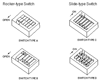
Rocker and Slide type DIP Switches are used in Sun products. Turn on a
Rocker-type switch by pressing down the end of the switch furthest from the
OPEN lettering on the switch. Turn on a Slide-type switch by sliding the
switch in the direction of the arrow on the switch. Switches 1 and 2 are
shown in the ON position in these illustrations.

Jumpers
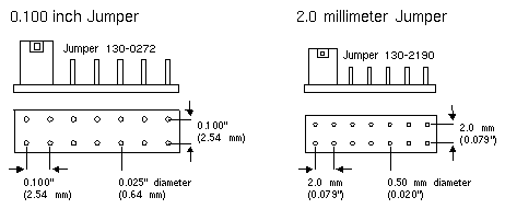
Jumpers are used to connect two pins of a Terminal Strip. Two sizes of
jumpers are used: 0.100 inch and 2.0 millimeter.

To program the EEPROM or NVRAM using the Sun PROM
Monitor, enter q followed by the hexadecimal address in
the EEPROM or NVRAM to open and display the contents.
Change the contents by typing in the new value followed by
a carriage return. To exit, type a space and <CR>, or a
"." and <CR>.
Common EEPROM or NVRAM Parameters
- Location 0x14 [Installed Memory]
- Amount of installed Memory in hexadecimal
-
- Location 0x15 [Tested Memory]
- Amount of memory to test during Power On Self-Test
-
- Location 0x16 [Monitor Screen Size]
- 00 = 1152x900 (standard resolution)
- 12 = 1024x1024 (1Kx1K)
- 13 = 1600x1280 (high resolution) (see 0x50 & 0x51)
- 14 = 1440x1440
- 15 = 1024x768 (low resolution)
-
- Location 0x17 [Watchdog Reset Action]
- 00 = Watchdog Reset returns to the PROM monitor
- 12 = Watchdog Reset causes a Power On Reset (default)
-
- Location 0x18 [Operating System Boot Device]
- 00 = polls devices (default)
- 12 = use EEPROM/NVRAM specified boot device
-
- Location 0x19 - 0x1a [SunOS Boot Device in ASCII]
-
| xy |
78 |
79 |
| xd |
78 |
64 |
| sd |
73 |
64 |
| ie |
69 |
65 |
| id |
69 |
64 |
| gn |
67 |
6e |
| le |
6c |
65 |
-
- Location 0x1b, 0x1c, and 0x1d [Controller, Unit, Partition]
-
-
- Location 0x1f [Primary Terminal]
- 00 = Monochrome Frame Buffer
- 10 = Serial Port A
- 11 = Serial Port B
- 12 = VMEbus and Sun-3/60 P4 Color Frame Buffers
- Configure locations 0x60c - 0x613 when VX and MVX Graphics Options
are installed.
- 20 = P4 Color Frame Buffer
-
- Location 0x20 [Power-Up Banner]
- 00 = Sun Banner
- 12 = Custom Banner
-
- Location 0x21 [Keyboard Click]
- 00 = turns keyboard click OFF
- 12 = turns keyboard click ON (default)
-
- Location 0x22 - 0x23 [Diagnostic Boot Device in ASCII]
-
| xy |
78 |
79 |
| xd |
78 |
64 |
| sd |
73 |
64 |
| ie |
69 |
65 |
| id |
69 |
64 |
| gn |
67 |
6e |
| le |
6c |
65 |
-
- Location 0x24, 0x25, and 0x26 [Controller, Unit, Partition]
-
-
- Location 0x28 - 0x4f [Diagnostic Boot Path]
- These 40 bytes represent the ASCII values for the desired
diagnostic boot path.
-
- Location 0x50 [Hi Res # Columns]
- 50 = 80 columns (standard display)
- 78 = 120 columns (full screen display)
-
- Location 0x51 [Hi Res # Rows]
- 22 = 34 rows (standard display)
- 30 = 48 rows (full screen display)
-
- Location 0x58 [Serial Port A Default Baud Rate]
- 00 = uses 9600 baud
- 12 = uses EEPROM/NVRAM defined baud rate
-
- Location 0x59 - 0x5a [Serial Port A Baud Rate]
-
| 1200 baud |
04 |
b0 |
| 4800 baud |
12 |
c0 |
| 9600 baud |
25 |
80 |
-
- Location 0x5b [Serial Port A DTR/RTS]
- 00 = asserts DTR and RTS signals
- 12 = does not assert DTR and RTS signals
-
- Location 0x60 [Serial Port B Default Baud Rate]
- 00 = uses 9600 baud
- 12 = uses EEPROM/NVRAM defined baud rate
- In the diag position, port B is set to output at 1200 baud.
- The setting of location 0x60 - 0x62 is ignored.
-
- Location 0x61 - 0x62 [Serial Port B Baud Rate]
-
| 1200 baud |
04 |
b0 |
| 4800 baud |
12 |
c0 |
| 9600 baud |
25 |
80 |
-
- Location 0x63 [Serial Port B DTR/RTS]
- 00 = asserts DTR and RTS signals
- 02 = does not assert DTR and RTS signals
-
- Location 0x18f [LogoType]
- 00 = Sun
- 06 = 3D for CG6
- 12 = Custom
-
- Location 0x492 [Password Mode Select]
Sun-3 and Sun-4 Boot PROM >= 2.7.1
- 5E = fully secure mode
- 01 = command secure mode
- All else = non-secure mode
-
- Location 0x493-0x49a [Password Bytes]
Sun-3 and Sun-4 Boot PROM >= 2.7.1
- 8 bytes of password in ASCII
-
- If the PROM Rev level is 2.8, enter a @ character before
each letter of the password. Enter one letter before each location, followed
by <Return>. If the password is less than 8 letters, enter
00 in the remaining locations. The hexidecimal value of
the letters can also be used to enter the password.
-
- Location 0x60c - 0x60f [VX and MVX Options Boot Code]
- 31 40 00 00 = Use the VX/MVX as the system console
-
- Location 0x610 - 0x613 [VX and MVX Options Bus Type]
- FC 00 00 00 = Use the VX/MVX as the system console
References
- Sun Bootstrap PROM Security Features User's Guide for the Sun
Workstation, 800-8836.
- Sun Workstation Bootstrap PROM Security Features User's Guide,
800-8843.
- Sun-3/80 Self-Tests and Monitor Commands, 800-5027.
- SPARCsystem 300 Series Self-Tests and Monitor Commands,
800-4950.
- SPARCsystem 400 Series Self-Tests and Monitor Commands,
800-4833.
- PROM User's Manual, 800-1736.
- EEPROM Users Guide for Sun-3, Sun-4, and SPARCsystems 300/400,
800-3512.
- Boot PROM User's Guide, 800-4852.
Last updated: December 2, 1996
Comments and Suggestions
|

