SPARCstation 10
| 501-2274 |
0MB Model 20 FRU
w/o MBus Module |
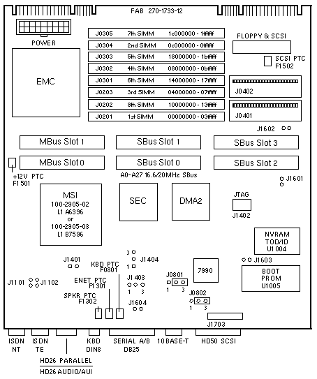
FAB 270-1733-12 Jumper Settings
| JUMPER |
PINS |
SETTING |
DESCRIPTION |
J0801
J0802
J0801
J0802 |
1-2
1-2
2-3
2-3 |
In
In
In*
In* |
Select RS-232 (+12V)
Select RS-232 (-12V)
Select RS-423
Select RS-423 |
J1101
J1102
J1101
J1102 |
1-2
1-2
1-2
1-2 |
Out*
Out*
In
In |
100 Ohm ISDN termination disabled
100 Ohm ISDN termination disabled
100 Ohm TE termination enabled
100 Ohm TE termination enabled |
J1401
J1403
J1404
- - -
J1401
J1403
J1404 |
1-2
2-3
2-3
- - -
1-2
1-2
1-2 |
In
In
In
- - -
Out
In
In |
Select 66MHz clock
Select 66MHz clock
Select 66MHz clock
- - - - - - - - - -
Select 80MHz clock
Select 80MHz clock
Select 80MHz clock |
| J1402 |
1-2
3-4
5-6
7-8 |
Out
Out
Out
Out |
JTAG test point
JTAG test point
JTAG test point
JTAG test point |
J1601
J1602
J1603
J1604 |
1-2
1-2
1-2
1-2 |
In/Out
In/Out
In/Out
In/Out |
GND test point
GND test point
GND test point
GND test point |
| J1703 |
1-2
3-4
5-6
7-8
9-10
11-12
13-14
15-16
17-18
19-20
21-22
23-24 |
Out
Out
Out
Out
Out
Out
Out
Out
Out
Out
Out
Out |
Manufacturing jumper mousei
Manufacturing jumper kbdi
Manufacturing jumper kbdo
Manufacturing jumper edgeon
Manufacturing jumper ptxdb
Manufacturing jumper prxdb
Manufacturing jumper ptxda
Manufacturing jumper prxda
Manufacturing jumper tpe<0>
Manufacturing jumper tpe<1>
Manufacturing jumper tpe<2>
Manufacturing jumper tpe<3> |
|
| * Default setting |
| 501-2274 |
0MB Model 20 FRU
w/o MBus Module |
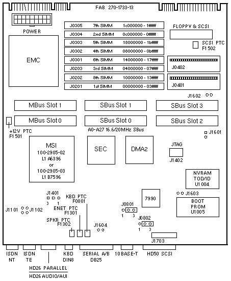
FAB 270-1733-13 Jumper Settings
| JUMPER |
PINS |
SETTING |
DESCRIPTION |
J0801
J0802
J0801
J0802 |
1-2
1-2
2-3
2-3 |
In
In
In*
In* |
Select RS-232 (+12V)
Select RS-232 (-12V)
Select RS-423
Select RS-423 |
J1101
J1102
J1101
J1102 |
1-2
1-2
1-2
1-2 |
Out*
Out*
In
In |
100 Ohm ISDN termination disabled
100 Ohm ISDN termination disabled
100 Ohm ISDN termination enabled
100 Ohm ISDN termination enabled |
| J1401 |
1-2
2-3 |
In
In |
Select 80MHz clock
Select 66MHz clock |
| J1402 |
1-2
3-4
5-6
7-8 |
Out
Out
Out
Out |
JTAG test point
JTAG test point
JTAG test point
JTAG test point |
J1601
J1602
J1603
J1604 |
1-2
1-2
1-2
1-2 |
In/Out
In/Out
In/Out
In/Out |
GND test point
GND test point
GND test point
GND test point |
| J1703 |
1-2
3-4
5-6
7-8
9-10
11-12
13-14
15-16
17-18
19-20
21-22
23-24 |
Out
Out
Out
Out
Out
Out
Out
Out
Out
Out
Out
Out |
Manufacturing jumper mousei
Manufacturing jumper kbdi
Manufacturing jumper kbdo
Manufacturing jumper edgeon
Manufacturing jumper ptxdb
Manufacturing jumper prxdb
Manufacturing jumper ptxda
Manufacturing jumper prxda
Manufacturing jumper tpe<0>
Manufacturing jumper tpe<1>
Manufacturing jumper tpe<2>
Manufacturing jumper tpe<3> |
|
| * Default setting |
| 501-1733 |
0MB FRU
w/o MBus Module |
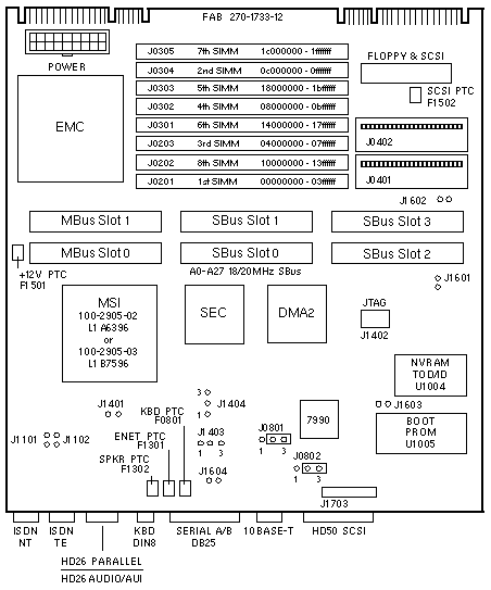
FAB 270-1733-12 Jumper Settings
| JUMPER |
PINS |
SETTING |
DESCRIPTION |
J0801
J0802
J0801
J0802 |
1-2
1-2
2-3
2-3 |
In
In
In*
In* |
Select RS-232 (+12V)
Select RS-232 (-12V)
Select RS-423
Select RS-423 |
J1101
J1102
J1101
J1102 |
1-2
1-2
1-2
1-2 |
Out*
Out*
In
In |
100 Ohm ISDN termination disabled
100 Ohm ISDN termination disabled
100 Ohm ISDN termination enabled
100 Ohm ISDN termination enabled |
J1401
J1403
J1404
- - -
J1401
J1403
J1404 |
1-2
2-3
2-3
- - -
1-2
1-2
1-2 |
In
In
In
- - -
Out
In
In |
Select 72MHz clock
Select 72MHz clock
Select 72MHz clock
- - - - - - - - - -
Select 80MHz clock
Select 80MHz clock
Select 80MHz clock |
| J1402 |
1-2
3-4
5-6
7-8 |
Out
Out
Out
Out |
JTAG test point
JTAG test point
JTAG test point
JTAG test point |
J1601
J1602
J1603
J1604 |
1-2
1-2
1-2
1-2 |
In/Out
In/Out
In/Out
In/Out |
GND test point
GND test point
GND test point
GND test point |
| J1703 |
1-2
3-4
5-6
7-8
9-10
11-12
13-14
15-16
17-18 |
Out
Out
Out
Out
Out
Out
Out
Out
Out |
Manufacturing jumper mousei
Manufacturing jumper kbdi
Manufacturing jumper kbdo
Manufacturing jumper edgeon
Manufacturing jumper ptxdb
Manufacturing jumper prxdb
Manufacturing jumper ptxda
Manufacturing jumper prxda
Manufacturing jumper tpe<0>
|
|
| * Default setting |
| 501-1733 |
0MB FRU
w/o MBus Module |
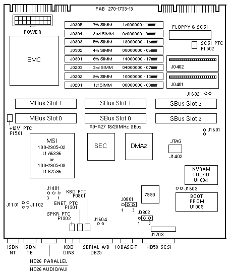
FAB 270-1733-13 Jumper Settings
| JUMPER |
PINS |
SETTING |
DESCRIPTION |
J0801
J0802
J0801
J0802 |
1-2
1-2
2-3
2-3 |
In
In
In*
In* |
Select RS-232 (+12V)
Select RS-232 (-12V)
Select RS-423
Select RS-423 |
J1101
J1102
J1101
J1102 |
1-2
1-2
1-2
1-2 |
Out*
Out*
In
In |
100 Ohm ISDN termination disabled
100 Ohm ISDN termination disabled
100 Ohm ISDN termination enabled
100 Ohm ISDN termination enabled |
| J1401 |
1-2
2-3 |
In
In |
Select 80MHz clock
Select 72MHz clock |
| J1402 |
1-2
3-4
5-6
7-8 |
Out
Out
Out
Out |
JTAG test point
JTAG test point
JTAG test point
JTAG test point |
J1601
J1602
J1603
J1604 |
1-2
1-2
1-2
1-2 |
In/Out
In/Out
In/Out
In/Out |
GND test point
GND test point
GND test point
GND test point |
| J1703 |
1-2
3-4
5-6
7-8
9-10
11-12
13-14
15-16
17-18
19-20
21-22
23-24 |
Out
Out
Out
Out
Out
Out
Out
Out
Out
Out
Out
Out |
Manufacturing jumper mousei
Manufacturing jumper kbdi
Manufacturing jumper kbdo
Manufacturing jumper edgeon
Manufacturing jumper ptxdb
Manufacturing jumper prxdb
Manufacturing jumper ptxda
Manufacturing jumper prxda
Manufacturing jumper tpe<0>
Manufacturing jumper tpe<1>
Manufacturing jumper tpe<2>
Manufacturing jumper tpe<3> |
|
| * Default setting |
| 501-2259 |
0MB FRU
w/o MBus Module |
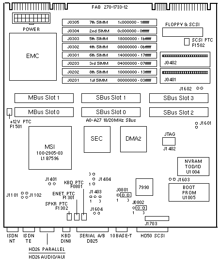
FAB 270-1733-12 Jumper Settings
| JUMPER |
PINS |
SETTING |
DESCRIPTION |
J0801
J0802
J0801
J0802 |
1-2
1-2
2-3
2-3 |
In
In
In*
In* |
Select RS-232 (+12V)
Select RS-232 (-12V)
Select RS-423
Select RS-423 |
J1101
J1102
J1101
J1102 |
1-2
1-2
1-2
1-2 |
Out*
Out*
In
In |
100 Ohm ISDN termination disabled
100 Ohm ISDN termination disabled
100 Ohm ISDN termination enabled
100 Ohm ISDN termination enabled |
J1401
J1403
J1404
- - -
J1401
J1403
J1404 |
1-2
2-3
2-3
- - -
1-2
1-2
1-2 |
In
In
In
- - -
Out
In
In |
Select 72MHz clock
Select 72MHz clock
Select 72MHz clock
- - - - - - - - - -
Select 80MHz clock
Select 80MHz clock
Select 80MHz clock |
| J1402 |
1-2
3-4
5-6
7-8 |
Out
Out
Out
Out |
JTAG test point
JTAG test point
JTAG test point
JTAG test point |
J1601
J1602
J1603
J1604 |
1-2
1-2
1-2
1-2 |
In/Out
In/Out
In/Out
In/Out |
GND test point
GND test point
GND test point
GND test point |
| J1703 |
1-2
3-4
5-6
7-8
9-10
11-12
13-14
15-16
17-18
19-20
21-22
23-24 |
Out
Out
Out
Out
Out
Out
Out
Out
Out
Out
Out
Out |
Manufacturing jumper mousei
Manufacturing jumper kbdi
Manufacturing jumper kbdo
Manufacturing jumper edgeon
Manufacturing jumper ptxdb
Manufacturing jumper prxdb
Manufacturing jumper ptxda
Manufacturing jumper prxda
Manufacturing jumper tpe<0>
Manufacturing jumper tpe<1>
Manufacturing jumper tpe<2>
Manufacturing jumper tpe<3> |
|
| * Default setting |
| 501-2259 |
0MB FRU
w/o MBus Module |
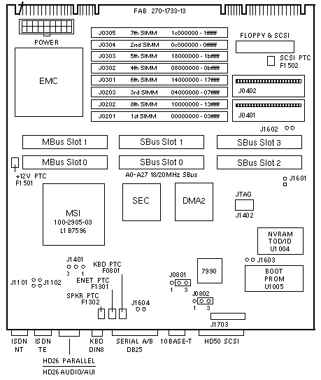
FAB 270-1733-13 Jumper Settings
| JUMPER |
PINS |
SETTING |
DESCRIPTION |
J0801
J0802
J0801
J0802 |
1-2
1-2
2-3
2-3 |
In
In
In*
In* |
Select RS-232 (+12V)
Select RS-232 (-12V)
Select RS-423
Select RS-423 |
J1101
J1102
J1101
J1102 |
1-2
1-2
1-2
1-2 |
Out*
Out*
In
In |
100 Ohm ISDN termination disabled
100 Ohm ISDN termination disabled
100 Ohm ISDN termination enabled
100 Ohm ISDN termination enabled |
| J1401 |
1-2
2-3 |
In
In |
Select 80MHz clock
Select 72MHz clock |
| J1402 |
1-2
3-4
5-6
7-8 |
Out
Out
Out
Out |
JTAG test point
JTAG test point
JTAG test point
JTAG test point |
J1601
J1602
J1603
J1604 |
1-2
1-2
1-2
1-2 |
In/Out
In/Out
In/Out
In/Out |
GND test point
GND test point
GND test point
GND test point |
| J1703 |
1-2
3-4
5-6
7-8
9-10
11-12
13-14
15-16
17-18
19-20
21-22
23-24 |
Out
Out
Out
Out
Out
Out
Out
Out
Out
Out
Out
Out |
Manufacturing jumper mousei
Manufacturing jumper kbdi
Manufacturing jumper kbdo
Manufacturing jumper edgeon
Manufacturing jumper ptxdb
Manufacturing jumper prxdb
Manufacturing jumper ptxda
Manufacturing jumper prxda
Manufacturing jumper tpe<0>
Manufacturing jumper tpe<1>
Manufacturing jumper tpe<2>
Manufacturing jumper tpe<3> |
|
| * Default setting |
| 501-2365 |
501-2774 |
0MB FRU
w/o MBus Module |
0MB FRU
w/o MBus Module |
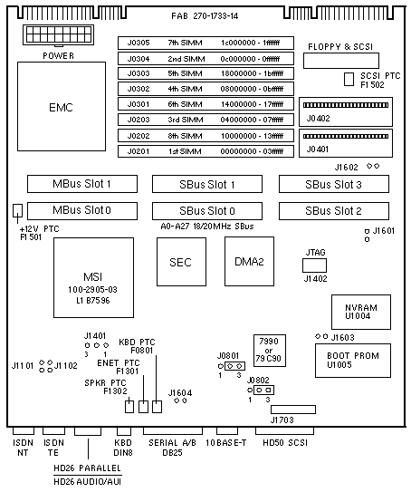
Ethernet Controller Notes
- The AM7990 is installed on CPU <=501-2365-03.
- The AM7990 or AM79C90 is installed on CPU >=501-2365-04.
- The AM7990 is installed on CPU 501-2774-xx.
FAB 270-1733-14 Jumper Settings
| JUMPER |
PINS |
SETTING |
DESCRIPTION |
J0801
J0802
J0801
J0802 |
1-2
1-2
2-3
2-3 |
In
In
In*
In* |
Select RS-232 (+12V)
Select RS-232 (-12V)
Select RS-423
Select RS-423 |
J1101
J1102
J1101
J1102 |
1-2
1-2
1-2
1-2 |
Out
Out
In*
In* |
100 Ohm ISDN termination disabled
100 Ohm ISDN termination disabled
100 Ohm ISDN termination enabled
100 Ohm ISDN termination enabled |
| J1401 |
1-2
2-3 |
In
In |
Select 80MHz clock
Select 72MHz clock |
| J1402 |
1-2
3-4
5-6
7-8 |
Out
Out
Out
Out |
JTAG test point
JTAG test point
JTAG test point
JTAG test point |
J1601
J1602
J1603
J1604 |
1-2
1-2
1-2
1-2 |
In/Out
In/Out
In/Out
In/Out |
GND test point
GND test point
GND test point
GND test point |
| J1703 |
1-2
3-4
5-6
7-8
9-10
11-12
13-14
15-16
17-18
19-20
21-22
23-24 |
Out
Out
Out
Out
Out
Out
Out
Out
Out
Out
Out
Out |
Manufacturing jumper mousei
Manufacturing jumper kbdi
Manufacturing jumper kbdo
Manufacturing jumper edgeon
Manufacturing jumper ptxdb
Manufacturing jumper prxdb
Manufacturing jumper ptxda
Manufacturing jumper prxda
Manufacturing jumper tpe<0>
Manufacturing jumper tpe<1>
Manufacturing jumper tpe<2>
Manufacturing jumper tpe<3> |
|
| * Default setting |
The Configured System Boards chart shows the manufacturing history of
factory configured SS10 System Board part numbers. Use the chart to determine
the compatibility of a factory configured system board with the GT and ZX
Graphics Options.
Configured system boards with the SM51 SuperSPARC Module were only built using
0MB System Boards 501-2259 or 501-2365. The SM51 Module is compatible with all
0MB System Boards and all FABs. Upgrades, including 50MHz and 60MHz modules, do
not require a system board exchange.
PART
NUMBER |
MEM
SIZE |
SPARC
MODULE |
0MB FRU |
FAB |
OPTION |
| GT |
ZX |
| 501-2241-01 Rev 50 |
32MB |
SM20 |
501-2274 |
270-1733-12 |
N |
N |
| 501-2241-03 Rev 56 |
32MB |
SM20 |
501-2274 |
270-1733-12 |
Y |
Y |
| 501-2241-03 Rev 57 |
32MB |
SM20 |
501-2274 |
270-1733-13 |
Y |
Y |
|
| 501-2260-01 Rev 50 |
32MB |
SM30 |
501-2259 |
270-1733-12 |
N |
N |
| 501-2260-02 Rev 56 |
32MB |
SM30 |
501-2259 |
270-1733-12 |
Y |
Y |
|
| 501-1938-xx Rev xx |
32MB |
SM30 |
501-1733 |
270-1733-xx |
N |
N |
| 501-1938-07 Rev 56 |
32MB |
SM30 |
501-1733 |
270-1733-12 |
Y |
Y |
| 501-1938-07 Rev 57 |
32MB |
SM30 |
501-2259 |
270-1733-13 |
Y |
Y |
| 501-1938-09 Rev 50 |
32MB |
SM30 |
501-2365 |
270-1733-14 |
Y |
Y |
|
| 501-2237-xx Rev xx |
0MB |
SM30 |
501-1733 |
270-1733-12 |
N |
N |
| 501-2237-04 Rev 50 |
0MB |
SM30 |
501-2259 |
270-1733-12 |
Y |
Y |
| 501-2237-05 Rev 50 |
0MB |
SM30 |
501-2259 |
270-1733-13 |
Y |
Y |
| 501-2237-07 Rev 50 |
0MB |
SM30 |
501-2365 |
270-1733-14 |
Y |
Y |
|
| 501-2295-01 Rev 50 |
32MB |
SM40 |
501-1733 |
270-1733-12 |
N |
N |
| 501-2295-01 Rev 51 |
32MB |
SM40 |
501-1733 |
270-1733-12 |
Y |
Y |
| 501-2295-01 Rev 52 |
32MB |
SM40 |
501-2259 |
270-1733-13 |
Y |
Y |
| 501-2295-03 Rev 50 |
32MB |
SM40 |
501-2365 |
270-1733-14 |
Y |
Y |
|
| 501-2375-xx Rev xx |
32MB |
SM40 |
501-2365 |
270-1733-14 |
Y |
Y |
| 501-2414-01 Rev 50 |
0MB |
SM40 |
501-2259 |
270-1733-13 |
Y |
Y |
| 501-2414-01 Rev 51 |
0MB |
SM40 |
501-2259 |
270-1733-14 |
Y |
Y |
|
| 501-2261-01 Rev 50 |
32MB |
SM41 |
501-2259 |
270-1733-12 |
N |
N |
| 501-2261-01 Rev 56 |
32MB |
SM41 |
501-2259 |
270-1733-13 |
Y |
Y |
|
| 501-1941-xx Rev xx |
32MB |
SM41 |
501-1733 |
270-1733-xx |
N |
N |
| 501-1941-05 Rev 59 |
32MB |
SM41 |
501-1733 |
270-1733-12 |
N |
N |
| 501-1941-05 Rev 60 |
32MB |
SM41 |
501-2259 |
270-1733-13 |
Y |
Y |
| 501-1941-07 Rev 50 |
32MB |
SM41 |
501-2365 |
270-1733-14 |
Y |
Y |
|
| 501-2238-xx Rev xx |
0MB |
SM41 |
501-1733 |
270-1733-xx |
N |
N |
| 501-2238-03 Rev 50 |
0MB |
SM41 |
501-2259 |
270-1733-12 |
Y |
Y |
| 501-2238-04 Rev 50 |
0MB |
SM41 |
501-2259 |
270-1733-13 |
Y |
Y |
| 501-2238-06 Rev 50 |
0MB |
SM41 |
501-2365 |
270-1733-14 |
Y |
Y |
|
| 501-2413-01 Rev 50 |
0MB |
SM51 |
501-2259 |
270-1733-13 |
Y |
Y |
| 501-2413-01 Rev 51 |
0MB |
SM51 |
501-2365 |
270-1733-14 |
Y |
Y |
| 501-1940-xx Rev xx |
64MB |
SM51 |
501-2365 |
270-1733-14 |
Y |
Y |
| 501-2351-xx Rev xx |
64MB |
SM51 |
501-2365 |
270-1733-14 |
Y |
Y |
| 501-2389-xx Rev xx |
32MB |
SM51 |
501-2365 |
270-1733-14 |
Y |
Y |
| 501-1942-xx Rev xx |
64MB |
SM52 |
501-2365 |
270-1733-14 |
Y |
Y |
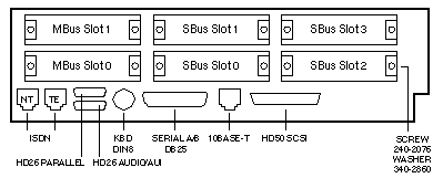
SPARCstation 10
System Board Backpanel and Connectors
SPARC
MODULE |
MODULES
INSTALLED |
SOLARIS
RELEASE |
SunOS
RELEASE |
| SM20 |
1 |
1.1 |
4.1.3 |
| SM30 |
1 |
1.1 |
4.1.3 |
| SM40 |
1 |
1.1 |
4.1.3 |
| SM40 |
2 |
2.2 |
5.2 |
| SM41 |
1 |
1.1 |
4.1.3 |
| SM41 |
2 |
2.1 |
5.1 |
| SM51 |
1 |
1.1 |
4.1.3 |
| SM51 |
2 |
2.1 |
5.1 |
| SM52x |
1 or 2 |
2.3 |
5.3 |
| SM61 |
1 |
1.1 |
4.1.3 |
| SM61 |
2 |
2.1 |
5.1 |
| SM71 |
1 |
1.1.1B |
4.1.3U1B |
| SM71 |
2 |
2.3 |
5.3 |
SPARC Module Notes
- Do NOT mix SPARC modules of different types or speeds.
- OBP 2.12 is required if two SM40s are installed.
- The 501-2219 SM40 supports single processor mode only.
- The 501-2358 SM40 supports dual processor mode.
- When adding a second SPARC module, disable the TERMPWR option on internal
disk drives with PTC protection. Failure to disable the disk drive TERMPWR
option may cause power supply over-current shutdown during power-up if SCSI
cable 530-1847-02 is installed.
- The 100MHz and 125MHz hyperSPARC Modules require OBP 2.19.
- SuperSPARC II modules require OBP 2.22.
- The 150MHz hyperSPARC Module requires OBP 2.25.
Hardware System Notes
- Use 16MB SIMM 501-1785, 501-2273, or 501-2479.
- Use 64MB SIMM 501-1930 or 501-2480.
- Install the highest capacity SIMM in Slot 0 under Solaris 1.x.
- The 270-1733-14 FAB has BABT approval for ISDN use in the UK.
- The 270-1733-14 FAB has BABT approval for X.25 use in the UK.
- The Maxtor 207MB Disk Drive requires firmware level 4.22 if it is connected
to the on-board SCSI bus.
- The +12V PTC is connected to Power Connector J1501, Pin-1.
GT and ZX Configuration Notes
- The GT and ZX Options are not supported on system boards with MSI Rev A
100-2905-02. The ASIC is marked LSI Logic L1A6396.
- The GT and ZX Options are supported on system boards with MSI Rev B
100-2905-03. The ASIC is marked LSI Logic L1B7596.
- MSI Rev B was installed by manufacturing on the following 0MB CPUs:
501-2274-06 Rev 50
501-1733-16 Rev 52
501-2259-05 Rev 52
501-2365-01 Rev 50
- MSI Rev B is not installed during the repair process unless the ASIC is
defective. Repaired boards may or may not have MSI Rev B.
- Picking is disabled when the ZX is used with MSI Rev A.
- A replacement CPU, order number UG-S10-MTHRBOARD, is available for
customers who purchase ZX as a standalone option for older SS10 systems.
Internal SCSI Bus Notes
- Disable the TERMPWR option on disk drives installed in the SS10.
- SCSI bus TERMPWR is grounded on internal cable 530-1847-02. Failure to
disable the TERMPWR option on disk drives with PTC protection may cause power
supply over-current shutdown during power-up if SCSI cable 530-1847-02 is
installed.
- SCSI bus TERMPWR is grounded on internal cable 530-1847-02. Internal disk
drives with fused TERMPWR protection will blow the fuse if the disk drive
TERMPWR option is enabled. The TERMPWR option is not needed by the internal
SCSI bus.
- TERMPWR on the internal SCSI bus is not connected to TERMPWR on the
external SCSI bus.
- Regulated termination at J0107 on the internal cable receives power from
the SS10 CPU and is not connected to Pin-26 on the disk drive.
- The inner surface of the SS10 chassis is conductive. Use grommet 330-1390,
or bracket 340-2939 with grommet 330-1717 and grommet 330-1390 to mount an
internal disk drive. Damage to the disk drive may occur if this mounting
hardware is not used.
References
 SPARCstation 10 Installation Guide, 800-6313.
- Hardware Owner's Guide, 801-2175.
|

