Sun StorageTek[tm] 6140 / Sun[tm] Storage
6180 LEDs
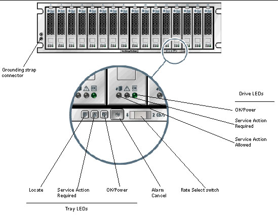
6140 / 6180 Controller Tray LEDs and Indicators
(Front View)
Note - A
tray LED icon may not be visible
unless the LED is illuminated.
|
Back to Top
6140 / 6180 Controller Tray LEDs and Components
(Front)
Back to Top
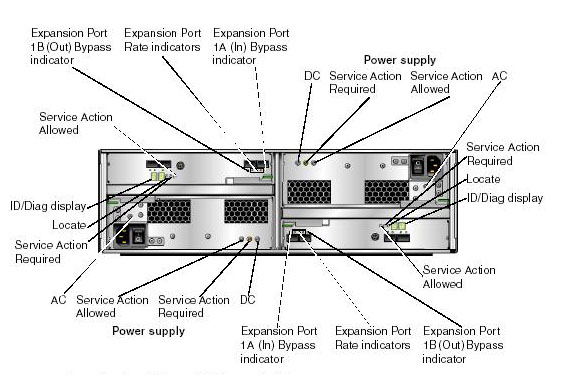
6140 Controller Tray
LEDs and Indicators (Back View)
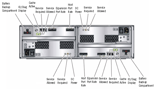
6180 Controller Tray LEDs and Indicators
(Back View)
Back to Top
6140 / 6180 Controller Tray LEDs and Indicators (Back)
|
LED/Indicator
|
Icon
|
Color
|
State
|
Description
|
| Power Supply LED
|
DC
|
 |
|
On
|
Correct DC power output
|
|
Service Action Required
|
 |
Amber
|
On
|
Power supply requires service. |
Off
|
Power supply does not require service. |
|
Service Action Allowed
|

|
Blue
|
On
|
Service action OK
|
Off
|
Service action NOT OK |
|
AC
|
 |
|
On
|
AC power being supplied to controller
|
|
Controller LEDs
|
|
ID/Diag display
|
Seven-segment readouts indicate the ID of the tray and fault diagnostic
status codes. See LED Status Codes for
definitions of the codes.
|
|
Cache Active
|
 |
Green
|
On
|
Data is in the cache.
|
Off
|
All data written to disk. Cache is empty. |
|
Service Action Required
|
|
Amber
|
On
|
Controller requires service.
|
Off
|
Controller does not require service. |
|
Service Action Allowed
|
|
Blue
|
On
|
Service action OK
|
Off
|
Controller engaged. Service action
NOT OK
|
|
Controller Indicator
|
|
6140 Host Port Rate
|
 |
The combined display indicates the host port link rate for the tray:
-
LED 1 On, LED 2 On - 4 Gbits/second
-
LED 1 Off, LED 2 On - 2 Gbits/second
-
LED 1 On, LED 2 Off - 1 Gbits/second
|
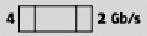
| 6180 Host Port Rate |
|
The combined display indicates the host port link rate for the tray:
- LED 2 On = 2 Gbits/second
- LED 4 On = 4 Gbits/second
- LED 2 and LED 4 On = 8Gbits/second
|
|
6140 Expansion Port Rate
|
 |
The combined display indicates the expansion port link rate for the tray:
-
LED 4 On, LED 2 Off - 4 Gbits/second
-
LED 4 Off, LED 2 On - 2 Gbits/second
|
| 6180 Expansion Port Rate |
|
The combined display indicates the host port link rate for the tray:
- LED 4 On, LED 2 On = 4Gbits/second
- LED 4 Off, LED 2 On = 2 Gbits/second
|
|
Expansion Port Bypass
|
 |
Amber
|
On
|
No valid device is detected and that the drive port is bypassed.
|
Off
|
No plug-in (SFP) transceiver installed
or port enabled. |
|
Ethernet Link Activity
|
On upper left-side of Ethernet connector |
Green
|
On
|
Active connection.
|
Off
|
No active connection. |
|
Ethernet Link Speed
|
On upper right-side of Ethernet connector |
Green
|
On |
100BaseTX connected
|
Off
|
(when Ethernet Status LED is on) 10BaseT
connected |
Back to Top
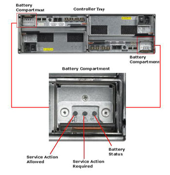
Battery Backup Compartment
Shows the location of the battery compartments on the controller and identifies
the LEDs on the compartment.
|
6140 Battery Compartment
|
6180 battery Compartment
|
 |
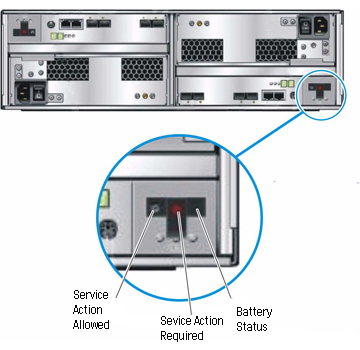 |
LEDs on the back of each battery backup compartment.
|
LED/Indicator
|
Icon
|
Color
|
State
|
Description
|
|
Service Action Allowed
|
|
Blue
|
On
|
Service action OK (it can be removed or disconnected)
|
Off
|
Battery is engaged. Service
action not OK.
|
|
Service Action Required
|
|
Amber
|
On
|
Battery requires replacement.
|
Off
|
Battery does not require
replacement |
|
Battery Status
|

|
Green
|
On
|
Battery is fully charged.
|
Slow Blink
|
Battery is charging |
Off
|
Battery is discharged or off |
Back to Top
LEDs at the
back of the expansion tray.
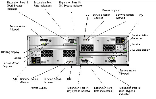
LEDs and indicators at the back of the expansion tray.
|
LED/Indicator
|
Icon
|
Color
|
State
|
Description
|
|
Power Supply LED
|
|
DC
|
|
|
On
|
The correct DC power output.
|
|
Service Action Required
|
|
Amber
|
On
|
power supply requires service.
|
Off
|
Power Supply does not require
service
|
|
Service Action Allowed
|
|
Steady
Blue
|
On
|
Service action OK
|
Off
|
power
supply engaged. Service action not OK.
|
|
AC
|
|
|
On
|
AC power is being supplied to the controller
power supply.
|
|
Expansion Tray LEDs
|
|
ID/Diag display
|
Seven-segment readouts indicate the ID of the tray and fault
diagnostic status codes. See LED
Status Codes for definitions of the codes
|
|
Locate
|
 |
White
|
On
|
Identifies the controller after initiation from
the management station.
|
|
Service Action
Required
|
|
Amber
|
On
|
Controller requires service.
|
Off
|
controller does not require
service. |
|
Service Action Allowed
|
|
Blue
|
On
|
Service action OK
|
Off
|
controller engaged. Service
action not OK.
|
|
Expansion Tray Indicator
|
|
Expansion Port Rate
|
|
The combined display indicates the expansion port link rate
for the tray:
-
LED 4 On, LED 2 Off - 4
Gbits/second
-
LED 4 Off, LED 2 On - 2 Gbits/second
|
|
Expansion Port Bypass
|
|
Amber
|
On
|
No valid device detected. Drive port is bypassed.
|
Off
|
There is no SFP
installed or port is enabled. |
Back to Top
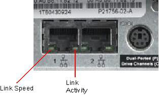
Meaning of ethernet LED ports:
LED/Indicator
|
Color
|
State
|
Description
|
Link Speed
|
Green
|
On
|
100 base T
|
Off
|
10 base T
|
Link Activity
|
Green
|
Off
|
No Link
|
On
|
Link Established
|
Blinking
|
Activity
|
Back to Top
LED Status Codes
The following is a list of the
meanings of the status codes that may display on the numerical LEDs
on the controller or expansion trays.
FF - ESM Boot Diagnostic executing
88 - This ESM is being held in Reset
by the other ESM
AA - ESM-A application is booting up
bb - ESM-B application is booting up
L0 - Mismatched ESM types
L2 - Persistent memory errors
L3 - Persistent hardware errors
L9 - Over Temperature
H1 - SFP Speed Mismatch (2 Gb/s SFP
installed when operating at 4 Gb/s)
H2 - Invalid/Incomplete Configuration
H3 - Maximum Reboot Attempts Exceeded
H4 - Cannot Communicate with Other ESM
H5 - Midplane Harness Failure
H6 - Firmware Failure
H7 - Current Enclosure Fibre Channel
Rate Different than Rate Switch
H8 - SFP(s) Present in Currently
Unsupported Slot (2A or 2B)
Back to Top
|