Ultra 80 / Enterprise 420R / Netra t 1400/1405
A27 / A33

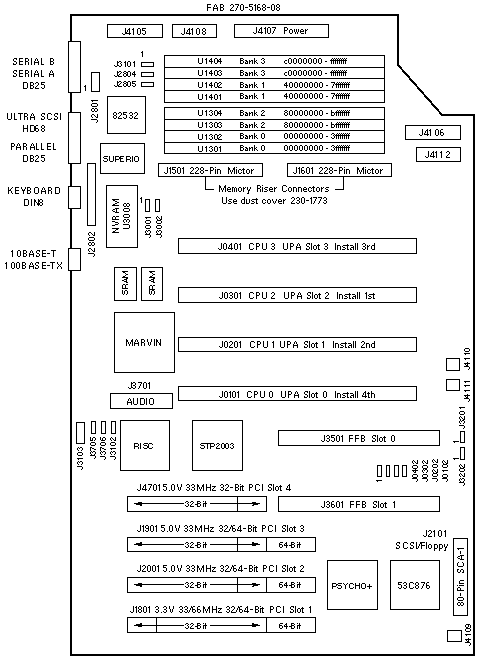
Jumper Settings
| JUMPER |
PINS |
SETTING |
DESCRIPTION |
| J0102 |
2-3 |
In |
Bypass CPU0 in scan chain |
| J0202 |
2-3 |
In |
Bypass CPU1 in scan chain |
| J0302 |
2-3 |
In |
Bypass CPU2 in scan chain |
| J0402 |
2-3 |
In |
Bypass CPU3 in scan chain |
| J2804 |
1-2
2-3 |
In
In |
RS-232 +12Vdc
RS-423 (default) |
| J2805 |
1-2
2-3 |
In
In |
RS-232 -12Vdc
RS-423 (default) |
| J3001 |
1-2
2-3 |
In
In |
FPROM write protected (default)
FPROM write enabled |
| J3002 |
1-2
2-3 |
In
In |
Select Flash PROM (default)
Select ROMBO |
| J3102 |
1-2
2-3 |
In
In |
FPROM high half booting
FPROM low half booting (default) |
| J3201 |
1-2
2-3 |
In
In |
÷3 mode (360MHz)
÷4 mode (400MHz/450MHz) |
| J3202 |
2-3 |
In |
(on -07/08 FAB, removed from -09) |
| J3705 |
1-2
2-3 |
In
In |
QAM WGS- to SPEAKER OUT- (default)
QAM WGS- to POWERON_L |
| J3706 |
1-2
2-3 |
In
In |
QAM WGS+ to SPEAKER OUT+ (default)
QAM WGS+ to SUPPLYTRIP_L |
|
Module Slot Numbering
| SOCKET |
INSTALL |
UPA |
OBP/OS |
| J0401 |
3rd |
UPA 3 |
CPU 3 |
| J0301 |
1st |
UPA 2 |
CPU 2 |
| J0201 |
2nd |
UPA 1 |
CPU 1 |
| J0101 |
4th |
UPA 0 |
CPU 0 |
PCI Slot Numbering
| SLOT |
BUS |
DEVICE TREE |
| 4 |
B |
pci@1f,4000/*@5,* |
| 3 |
B |
pci@1f,4000/*@2,* |
| 2 |
B |
pci@1f,4000/*@4,* |
| 1 |
A |
pci@1f,2000/*@1,* |
PCI Bus B shares the address/data bus with on-board Audio, Ethernet, Flash,
Floppy, Keyboard, Mouse, NVRAM, Parallel, SCSI, and Serial devices.
Miscellaneous Connectors
| CONNECTOR |
PINS |
DESCRIPTION |
| J2801 |
1-8 |
Serial test (factory use) |
| J2802 |
1-32 |
ROMBO (factory use) |
| J3101 |
1-2
2-3 |
Button XIR (factory use)
Button POR (factory use) |
| J3103 |
1-8 |
JSCC (factory use) |
| J4105 |
1-18 |
DC-DC Converter |
| J4106 |
1-14 |
Power Supply sense |
| J4107 |
1-28 |
Power Supply +3.3V and +5V |
| J4108 |
1-10 |
DC-DC converter |
| J4109 |
1-2 |
Fan power |
| J4110 |
1-2 |
Fan power |
| J4111 |
1-8 |
Interlock, LED, speaker, and power switch |
| J4112 |
1-10 |
DC power to internal peripherals |
System Codenames
| System |
Codename |
| Ultra 80 |
Quasar |
| Enterprise 420R |
Quahog |
| Netra t 1400/1405 |
Lightweight 3 |
Notes
- The minimum OS is 2.5.1 HW: 11/97, 2.6 HW: 5/98, or 7 HW: 8/99.
- The flash PROM is soldered to the system board.
- Use the Flash PROM Programming Utility to update the flash PROM.
- 64-Bit PCI boards do not fit into Slot 4. Connector J3601 interferes with
the 64-Bit PCI extension connector.
- DC-DC Converter 300-1407 connects to J4105 and J4108 on the
system board.
SCSI Bus Notes
- The internal SCSI bus is controlled by /pci@1f,4000/scsi@3.
- The external SCSI bus is controlled by /pci@1f,4000/scsi@3,1.
Memory Notes
- DIMMs are required on both the Riser Board and the System Board.
- Every populated bank must contain four same-size DIMMs. Four
same-size DIMMs are a "quad".
- To activate 2-way interleaving, quads must be installed in
banks 0 and 1, which are non-adjacent banks.
(A third quad may be installed in either remaining bank, but that
will disable interleaving.)
- To activate 4-way interleaving, all four banks must be populated
with quads.
- Each bank addresses 1GB of memory.
- Damage to the Mictor Connectors can occur if DIMMs are installed
or removed when the Riser Board is installed on the System Board.
References
 Ultra 80 Getting Started Guide, 805-6615.
 Ultra 80 Service Manual, 805-6618.
 Enterprise 420R Service Manual, 806-1080.
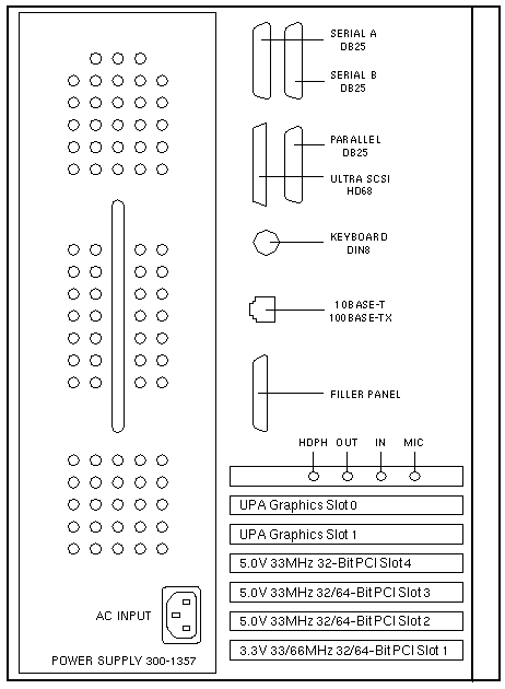
Rear View

|

