Ultra 1 Model 140E
A12-140
| 501-4291 |
501-4677 |
143MHz 0MB FRU
FAB 270-2486 |
143MHz 0MB FRU
FAB 270-4358 |

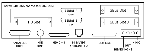
Backpanel and Connectors

Jumper Settings
| JUMPER |
PINS |
SETTING |
DESCRIPTION |
| J2002 |
1-2
2-3 |
In
In |
Select FPROM (default)
Select ROMBO |
| J2003 |
1-2
2-3 |
In
In |
FPROM write protect (default)
FPROM write enable |
| J2102 |
1-24 |
Out |
Serial port connector |
| J2103 |
1-8 |
Out |
Serial port edge test |
| J2104 |
1-2
2-3 |
In
In |
RS-232 -12Vdc
RS-423 (default) |
| J2105 |
1-2
2-3 |
In
In |
RS-232 +12Vdc
RS-423 (default) |
| J2201 |
1-2
2-3 |
Out
Out |
Button XIR
Button POR |
| J2202 |
1-8 |
Out |
ROMBO connector |
| J2203 |
1-8 |
Out |
JTAG connector |
| J2204 |
1-2
2-3 |
In
In |
FPROM high half booting
FPROM low half booting (default) |
| J3602 |
1-8 |
Out |
Ethernet edge test |
| J3603 |
1-8 |
Out |
Ethernet edge test |
Configured System Board
| PART # |
MEMORY |
SIMM |
# SIMMS |
| 501-3051 |
64MB |
32MB |
2 |
Notes
- The minimum operating system is Solaris 2.5 Hardware: 1/96.
- The flash PROM is soldered to the system board.
- Use the Flash PROM Programming Utility to update the flash PROM.
- UltraSPARC Fan 540-2761 was replaced by Heatsink 540-3361 and
Shield 540-3090 in May/June 1997.
References
 Sun Ultra 1 Series Installation Guide, 802-3825.
 Sun Ultra 1 Creator Series Service Manual, 802-4148.
 Flash PROM Programming Guide, 802-3233.
|

