Sun Microsystems, Inc.   Sun System Handbook - ISO 3.4 June 2011 Internal/Partner Edition
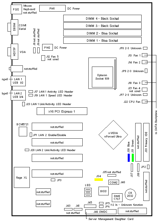
   Home | Current Systems | Former STK Products | EOL Systems | Components | General Info | Search | Feedback


Sun Fire X2100

375-3342 375-3427
Tyan Tomcat K8E S2865 Tyan Tomcat K8E S2865

Connectors

LOCATION DESCRIPTION
J17
J28
Front Panel LAN1 Link and Activity LED
Front Panel LAN2 Link and Activity LED
J19
J23
Front Panel LAN1 Speed LED
Front Panel LAN2 Speed LED
J30
J31
SATA1 to Backplane
SATA2 to Backplane
J34
J35
USB3 to Front I/O Board
USB4 not stuffed
J37
J38
SATA3 not used
SATA4 not used
J40 COM2 Serial Port not used
J45 LED/Power Control Header to Backplane
J46 SMDC to Backplane to Service Processor

Jumper Settings

LOCATION PINS SETTING DESCRIPTION
JP1 1-2 In LAN2 Enable (default)
JP2 1-2
2-3
In
In
Normal CMOS (default)
Clear CMOS (temporary setting only)
JP3 1-2
2-3
In
In
Select 3.3V PCI Slot (default)
Select 5.0V PCI Slot

Sun Fire X2100 Codename: Aquarius

Sun Fire X2100 Notes

  1. The minimum Solaris operating system is Solaris 10 3/05 HW1 x64.
  2. Install a single DIMM in any slot.
  3. A three DIMM memory configuration is not supported.
  4. Install the first DIMM pair in slots DIMM 1 and DIMM 2.
  5. Install the second DIMM pair in slots DIMM 3 and DIMM 4.

Clearing CMOS Notes

  1. Power off the system and disconnect the AC power cord.
  2. Move the jumper at JP2 to Pin 2 and Pin 3 for several seconds.
  3. Move the jumper at JP2 back to Pin 1 and Pin 2.
  4. Reconnect the AC power cord.

References

  1. Sun Fire X2100 Setup Guide, 819-3719.
  2. Sun Fire X2100 Getting Started, 819-3720.
  3. Sun Fire X2100 User Guide, 819-3721.
  4. Sun Fire X2100 Release Notes, 819-3722.

  Copyright � 2011 Sun Microsystems, Inc.  All rights reserved.
 Feedback