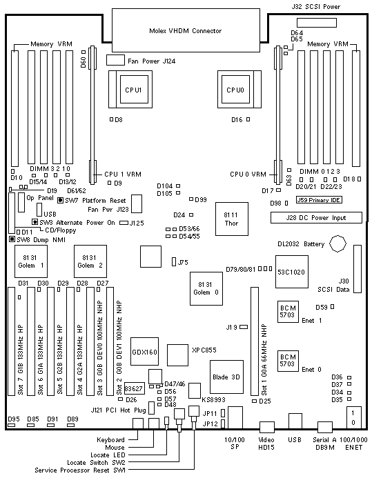
Sun Fire V40z
| 501-6883 |
Newisys S00401 or S01625
Motherboard 370-6929 + BIOS/Firmware
A57A-AA Chassis FRU 380-1010
MAC Address 00093dxxxxxx |

Jumpers
| LOCATION |
PINS |
SETTING |
DESCRIPTION |
| J19 |
1-2
1-2 |
Out
In |
Port A is Port A (default)
Port A is Service Processor Console |
| J125 |
1-2
2-3 |
In
In |
Clear CMOS on next boot
Normal CMOS Operation (default) |
| JP11 * |
1-2
1-2 |
In
Out |
BIOS Main Body Write Enabled (default)
BIOS Main Body Write controlled by BIOS or SP |
| JP12 * |
1-2
1-2 |
In
Out |
BIOS Boot Block Write Enabled (default)
BIOS Boot Block Write controlled by SP |
* Leave JP11 and JP12 in the default position.
HyperTransport/PCI Interrupt Map
| HT/PCI BRIDGE |
DEVICE |
IRQ A |
IRQ B |
IRQ C |
IRQ D |
| AMD-8131 Golem 0-B |
PCI Slot 2 |
x |
x |
x |
x |
| AMD-8131 Golem 0-B |
PCI Slot 3 |
x |
x |
x |
x |
| AMD-8131 Golem 0-A |
BCM5703 Ethernet 0 |
|
x |
|
|
| AMD-8131 Golem 0-A |
BCM5703 Ethernet 1 |
|
|
x |
|
| AMD-8131 Golem 0-A |
53C1020 SCSI |
|
|
|
x |
| AMD-8131 Golem 0-A |
PCI Slot 1 |
x |
x |
x |
x |
| AMD-8131 Golem 1-A |
PCI Slot 6 |
x |
x |
x |
x |
| AMD-8131 Golem 1-B |
PCI Slot 7 |
x |
x |
x |
x |
| AMD-8131 Golem 2-A |
PCI Slot 4 |
x |
x |
x |
x |
| AMD-8131 Golem 2-B |
PCI Slot 5 |
x |
x |
x |
x |
LEDs
| LOCATION |
COLOR |
STATE |
DESCRIPTION |
| LD8 |
Amber |
Fault |
CPU1 Status |
| LD9 |
Amber |
Fault |
CPU1 CPU VRM Status |
| LD10 |
Amber |
Fault |
CPU1 Memory VRM Status |
| LD11 |
Amber |
Fault |
DVD Status |
| LD12-15 |
Amber |
Fault |
CPU1 DIMM 0-3 Status |
| LD16 |
Amber |
Fault |
CPU0 Status |
| LD17 |
Amber |
Fault |
CPU0 CPU VRM Status |
| LD18 |
Amber |
Fault |
CPU0 Memory VRM Status |
| LD19 |
Amber |
Fault |
Floppy Status |
| LD20-23 |
Amber |
Fault |
CPU0 DIMM 0-3 Status |
| LD25-31 |
Amber |
Fault |
PCI Slot 1-7 Status |
| LD46 |
Green |
Normal |
Service Processor Status |
| LD48 |
Green |
Normal |
Service Processor Status |
| LD56 |
Green |
Normal |
Ethernet Connected to Upper MGMT Port |
| LD57 |
Green |
Normal |
Ethernet Connected to Lower MGMT Port |
| LD61 |
Green |
Normal |
CPU0 Memory VRM 2.5V Power OK |
| LD62 |
Green |
Normal |
CPU0 Memory VRM 1.25V Power OK |
| LD64 |
Green |
Normal |
CPU1 Memory VRM 2.5V Power OK |
| LD65 |
Green |
Normal |
CPU1 Memory VRM 1.25V Power OK |
Notes:
LED locations are abbreviated D on the system board illustration.
No information is available for other LED locations.
The normal state of D46 and D48 is an illuminated Green LED.
The normal state of D56 is a illuminated Green LED when a cable is connected.
The normal state of D57 is a illuminated Green LED when a cable is connected.
|
|
Sun Fire V40z Codename: Stinger4P |
Notes
- The Sun Fire V40z System Board is not a Field Replaceable Unit.
- System Board 501-6883 is installed in Chassis CRU 380-1010.
- Press F2 during bootup to enter the BIOS menu.
- BIOS updates are available at
 V40z SW 2.8.2 - Bundles. V40z SW 2.8.2 - Bundles.
- Due to AMD-8131 Errata 56, BIOS clocks down four-function PCI-X option
cards to 100MHz. BIOS 2.32.8.2 (NSV 2.3.0.6h/i) and later releases include
a workaround.
See  Release Notes
for details about Errata 56. Release Notes
for details about Errata 56.
References
 Sun Fire V20z and V40z Servers Installation Guide, 817-5246.
 Sun Fire V20z and V40z Servers User Guide, 817-5248.
 Sun Fire V20z and V40z Servers Management Guide, 817-5249.
 Sun Fire V20z and V40z Servers Release Notes, 819-1771.
 Sun Fire V20z and V40z Servers Troubleshooting Techniques and Diagnostics Guide, 817-7184.
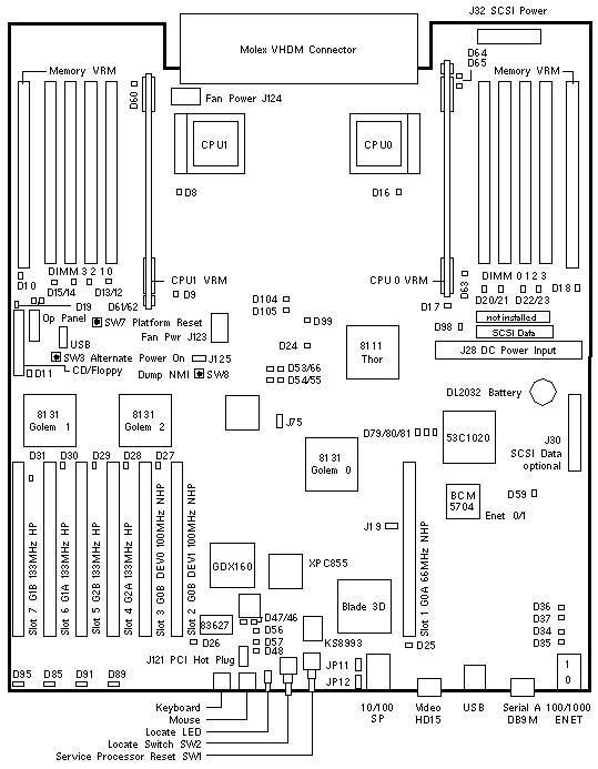
Sun Fire V40z
| 501-7139 |
Newisys S02399
Motherboard 370-7808 + BIOS/Firmware
A57B-AA Chassis FRU 380-1206
MAC Address 00093dxxxxxx |

Jumpers
| LOCATION |
PINS |
SETTING |
DESCRIPTION |
| J19 |
1-2
1-2 |
Out
In |
Port A is Port A (default)
Port A is Service Processor Console |
| J125 |
1-2
2-3 |
In
In |
Clear CMOS on next boot
Normal CMOS Operation (default) |
| JP11 * |
1-2
1-2 |
In
Out |
BIOS Main Body Write Enabled (default)
BIOS Main Body Write controlled by BIOS or SP |
| JP12 * |
1-2
1-2 |
In
Out |
BIOS Boot Block Write Enabled (default)
BIOS Boot Block Write controlled by SP |
* Leave JP11 and JP12 in the default position.
HyperTransport/PCI Interrupt Map
| HT/PCI BRIDGE |
DEVICE |
IRQ A |
IRQ B |
IRQ C |
IRQ D |
| AMD-8131 Golem 0-B |
PCI Slot 2 |
x |
x |
x |
x |
| AMD-8131 Golem 0-B |
PCI Slot 3 |
x |
x |
x |
x |
| AMD-8131 Golem 0-A |
BCM5703 Ethernet 0 |
|
x |
|
|
| AMD-8131 Golem 0-A |
BCM5703 Ethernet 1 |
|
|
x |
|
| AMD-8131 Golem 0-A |
53C1020 SCSI |
|
|
|
x |
| AMD-8131 Golem 0-A |
PCI Slot 1 |
x |
x |
x |
x |
| AMD-8131 Golem 1-A |
PCI Slot 6 |
x |
x |
x |
x |
| AMD-8131 Golem 1-B |
PCI Slot 7 |
x |
x |
x |
x |
| AMD-8131 Golem 2-A |
PCI Slot 4 |
x |
x |
x |
x |
| AMD-8131 Golem 2-B |
PCI Slot 5 |
x |
x |
x |
x |
LEDs
| LOCATION |
COLOR |
STATE |
DESCRIPTION |
| LD8 |
Amber |
Fault |
CPU1 Status |
| LD9 |
Amber |
Fault |
CPU1 CPU VRM Status |
| LD10 |
Amber |
Fault |
CPU1 Memory VRM Status |
| LD11 |
Amber |
Fault |
DVD Status |
| LD12-15 |
Amber |
Fault |
CPU1 DIMM 0-3 Status |
| LD16 |
Amber |
Fault |
CPU0 Status |
| LD17 |
Amber |
Fault |
CPU0 CPU VRM Status |
| LD18 |
Amber |
Fault |
CPU0 Memory VRM Status |
| LD19 |
Amber |
Fault |
Floppy Status |
| LD20-23 |
Amber |
Fault |
CPU0 DIMM 0-3 Status |
| LD25-31 |
Amber |
Fault |
PCI Slot 1-7 Status |
| LD46 |
Green |
Normal |
Service Processor Status |
| LD48 |
Green |
Normal |
Service Processor Status |
| LD56 |
Green |
Normal |
Ethernet Connected to Upper MGMT Port |
| LD57 |
Green |
Normal |
Ethernet Connected to Lower MGMT Port |
| LD61 |
Green |
Normal |
CPU0 Memory VRM 2.5V Power OK |
| LD62 |
Green |
Normal |
CPU0 Memory VRM 1.25V Power OK |
| LD64 |
Green |
Normal |
CPU1 Memory VRM 2.5V Power OK |
| LD65 |
Green |
Normal |
CPU1 Memory VRM 1.25V Power OK |
Notes:
LED locations are abbreviated D on the system board illustration.
No information is available for other LED locations.
The normal state of D46 and D48 is an illuminated Green LED.
The normal state of D56 is a illuminated Green LED when a cable is connected.
The normal state of D57 is a illuminated Green LED when a cable is connected.
|
|
Sun Fire V40z Codename: Stinger4P |
Notes
- The Sun Fire V40z System Board is not a Field Replaceable Unit.
- System Board 501-7139 is installed in Chassis CRU 380-1206.
- Dual Core Opteron requires BIOS 2.33.5.2 (Network Shared Volume 2.3.0.11).
BIOS 2.33.5.2 is installed in Chassis FRU 380-1206-02.
- Press F2 during bootup to enter the BIOS menu.
- BIOS updates are available at
 V40z SW 2.8.2 - Bundles. V40z SW 2.8.2 - Bundles.
- Due to AMD-8131 Errata 56, BIOS clocks down four-function PCI-X option
cards to 100MHz without notification.
See  Release Notes
for details about Errata 56. Release Notes
for details about Errata 56.
- The BCM5704 Ethernet Controller on System Board 501-7139 requires
an Install-Time Update (ITU) to install Solaris 9 4/04 x86 or
Solaris 9 9/04 x86.
Refer to FIN I1154.
References
 Sun Fire V20z and V40z Servers Installation Guide, 817-5246.
 Sun Fire V20z and V40z Servers User Guide, 817-5248.
 Sun Fire V20z and V40z Servers Management Guide, 817-5249.
 Sun Fire V20z and V40z Servers Release Notes, 819-1771.
 Sun Fire V20z and V40z Servers Troubleshooting Techniques and Diagnostics Guide, 817-7184.
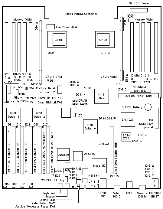
Sun Fire V40z
| 375-3438 |
Newisys unknown
A57C-AA Chassis FRU 380-1378
MAC Address 00093dxxxxxx
L |

Jumpers
| LOCATION |
PINS |
SETTING |
DESCRIPTION |
| J19 |
1-2
1-2 |
Out
In |
Port A is Port A (default)
Port A is Service Processor Console |
| J125 |
1-2
2-3 |
In
In |
Clear CMOS on next boot
Normal CMOS Operation (default) |
| JP11 * |
1-2
1-2 |
In
Out |
BIOS Main Body Write Enabled (default)
BIOS Main Body Write controlled by BIOS or SP |
| JP12 * |
1-2
1-2 |
In
Out |
BIOS Boot Block Write Enabled (default)
BIOS Boot Block Write controlled by SP |
* Leave JP11 and JP12 in the default position.
HyperTransport/PCI Interrupt Map
| HT/PCI BRIDGE |
DEVICE |
IRQ A |
IRQ B |
IRQ C |
IRQ D |
| AMD-8131 Golem 0-B |
PCI Slot 2 |
x |
x |
x |
x |
| AMD-8131 Golem 0-B |
PCI Slot 3 |
x |
x |
x |
x |
| AMD-8131 Golem 0-A |
BCM5703 Ethernet 0 |
|
x |
|
|
| AMD-8131 Golem 0-A |
BCM5703 Ethernet 1 |
|
|
x |
|
| AMD-8131 Golem 0-A |
53C1020 SCSI |
|
|
|
x |
| AMD-8131 Golem 0-A |
PCI Slot 1 |
x |
x |
x |
x |
| AMD-8131 Golem 1-A |
PCI Slot 6 |
x |
x |
x |
x |
| AMD-8131 Golem 1-B |
PCI Slot 7 |
x |
x |
x |
x |
| AMD-8131 Golem 2-A |
PCI Slot 4 |
x |
x |
x |
x |
| AMD-8131 Golem 2-B |
PCI Slot 5 |
x |
x |
x |
x |
LEDs
| LOCATION |
COLOR |
STATE |
DESCRIPTION |
| LD8 |
Amber |
Fault |
CPU1 Status |
| LD9 |
Amber |
Fault |
CPU1 CPU VRM Status |
| LD10 |
Amber |
Fault |
CPU1 Memory VRM Status |
| LD11 |
Amber |
Fault |
DVD Status |
| LD12-15 |
Amber |
Fault |
CPU1 DIMM 0-3 Status |
| LD16 |
Amber |
Fault |
CPU0 Status |
| LD17 |
Amber |
Fault |
CPU0 CPU VRM Status |
| LD18 |
Amber |
Fault |
CPU0 Memory VRM Status |
| LD19 |
Amber |
Fault |
Floppy Status |
| LD20-23 |
Amber |
Fault |
CPU0 DIMM 0-3 Status |
| LD25-31 |
Amber |
Fault |
PCI Slot 1-7 Status |
| LD46 |
Green |
Normal |
Service Processor Status |
| LD48 |
Green |
Normal |
Service Processor Status |
| LD56 |
Green |
Normal |
Ethernet Connected to Upper MGMT Port |
| LD57 |
Green |
Normal |
Ethernet Connected to Lower MGMT Port |
| LD61 |
Green |
Normal |
CPU0 Memory VRM 2.5V Power OK |
| LD62 |
Green |
Normal |
CPU0 Memory VRM 1.25V Power OK |
| LD64 |
Green |
Normal |
CPU1 Memory VRM 2.5V Power OK |
| LD65 |
Green |
Normal |
CPU1 Memory VRM 1.25V Power OK |
Notes:
LED locations are abbreviated D on the system board illustration.
No information is available for other LED locations.
The normal state of D46 and D48 is an illuminated Green LED.
The normal state of D56 is a illuminated Green LED when a cable is connected.
The normal state of D57 is a illuminated Green LED when a cable is connected.
|
|
Sun Fire V40z Codename: Stinger4P |
Notes
- The Sun Fire V40z System Board is not a Field Replaceable Unit.
- System Board 375-3438 is installed in Chassis CRU 380-1378.
- Dual Core Opteron requires BIOS 2.33.5.2 (Network Shared Volume 2.3.0.11).
BIOS 2.33.5.2 is installed in Chassis FRU 380-1206-02.
- Press F2 during bootup to enter the BIOS menu.
- BIOS updates are available at
 V40z SW 2.8.2 - Bundles. V40z SW 2.8.2 - Bundles.
- Due to AMD-8131 Errata 56, BIOS clocks down four-function PCI-X option
cards to 100MHz without notification.
See  Release Notes
for details about Errata 56. Release Notes
for details about Errata 56.
References
 Sun Fire V20z and V40z Servers Installation Guide, 817-5246.
 Sun Fire V20z and V40z Servers User Guide, 817-5248.
 Sun Fire V20z and V40z Servers Management Guide, 817-5249.
 Sun Fire V20z and V40z Servers Release Notes, 819-1771.
 Sun Fire V20z and V40z Servers Troubleshooting Techniques and Diagnostics Guide, 817-7184.
|

