Sun Blade 2500 (Silver)
| 375-3192 |
375-3193 |
375-3194 |
w/o Memory
w/o SB2500 Tray
w/o USIIIi |
0MB FRU
w SB2500 Tray
2× 1.600GHz USIIIi
Option 9016 |
0MB FRU
w SB2500 Tray
1× 1.600GHz USIIIi
Option 9015 |

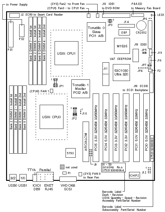
PCI Slot Numbering
| SLOT |
BUS |
DEVICE TREE |
| 5 |
2B |
pci@1f,70000/*@2,* |
| 4 |
2A |
pci@1e,60000/*@2,* |
| 3 |
1A |
pci@1c,60000/*@2,* |
| 2 |
1B |
pci@1d,70000/*@2,* |
| 1 |
2A |
pci@1e,60000/*@3,* |
| 0 |
2A |
pci@1e,60000/*@4,* |
Master PCI Bus 2A shares the address/data bus with ATA-100,
Audio, Flash, I2C, NVRAM, Parallel, Serial, and USB devices.
Slave PCI Bus 1A shares the address/data bus with the Ethernet controller.
Slave PCI Bus 1B shares the address/data bus with the SCSI controller.
Jumper Settings
| JUMPER |
PINS |
SETTING |
DESCRIPTION |
| J9 |
1-8 |
Out |
Test Header |
| J10 |
1-3 |
Out |
Reset Header |
| J11 |
1-46 |
n/a |
X86 Debug Header |
| J12 |
1-8 |
Out |
JTAG Header |
| J14 |
50 |
n/a |
Unused 50-Pin Header |
| J16 |
3 |
n/a |
Speaker Header |
| J19 |
3 |
n/a |
Glow Logo Header (not used) |
| JP1 |
1-2
7-8
9-10 |
In
In
In |
CPU1 1.4V Core VID[4:0] Bit 0 (00110)
CPU1 1.4V Core VID[4:0] Bit 3 (00110)
CPU1 1.4V Core VID[4:0] Bit 4 (00110) |
| JP2 |
1-2
7-8
9-10 |
In
In
In |
CPU0 1.4V Core VID[4:0] Bit 0 (00110)
CPU0 1.4V Core VID[4:0] Bit 3 (00110)
CPU0 1.4V Core VID[4:0] Bit 4 (00110) |
| JP3 |
1-2
3-4
5-6 |
Out
Out
In |
1.600GHz CONFIG[2:0] Bit 0 (011)
1.600GHz CONFIG[2:0] Bit 1 (011)
1.600GHz CONFIG[2:0] Bit 2 (011) |
| JP4 |
1-8 |
Out |
Unknown |
| JP5 |
1-2
1-2 |
In
Out |
FPROM low half booting (default)
FPROM high half booting (flash recovery) |
| JP6 |
1-2 |
Out |
Clear CMOS when installed |
| JP7 |
1-2
1-2 |
In
Out |
FPROM write enabled (default)
FPROM write protected |
|
Sun Blade 2500 (Silver) Codename: Enchilada+ |
Notes
- The minimum operating system is Solaris 8 2/04 or Solaris 9 9/04.
- The Sun Blade 2500 serial number and factory configuration label is
located on the upper left side of the front bezel and on the rear of
the chassis.
Memory Notes
- The minimum memory is two CPU0 DIMMs.
- CPU1 does not require memory in slots DIMM 4/5 or 6/7.
- At least two CPU1 DIMMs are recommended if CPU1 is installed.
- The memory installation sequence is Bank 2 then Bank 0.
- Bank, Rank, DIMM, and XOR Interleaving is supported.
- Only CPU 0 DIMMs are accessible in a single CPU system (CPU 0).
- Memory is mapped globally and is accessible by either CPU in a dual-CPU
system.
- UltraSPARC IIIi supports single bank and dual bank DDR-1 SDRAM DIMMs.
- Two DIMMs of the same bank size (single or dual) and memory size
form a bank.
- Memory error reporting identifies a failing Bank, not a single failing DIMM.
References
 Sun Blade 2500 Troubleshooting Card, 817-5115.
 Sun Blade 2500 Service, Diagnostics, and Troubleshooting Manual, 817-5117.
 Sun Blade 2500 Getting Started, 817-5119.
 Sun Blade 2500 Product Notes, 817-5121.
|

